 |
ac5wzw00001018
STEERING WHEEL AND COLUMN REMOVAL/INSTALLATION
id061300801400
1. Remove the driver-side front scuff plate. (See FRONT SCUFF PLATE REMOVAL/INSTALLATION.)
2. Remove the driver-side front side trim. (See FRONT SIDE TRIM REMOVAL/INSTALLATION.)
3. Remove the car-navigation unit (with car navigation system). (See CAR-NAVIGATION UNIT REMOVAL/INSTALLATION.)
4. Remove the switch panel. (See SWITCH PANEL REMOVAL/INSTALLATION.)
5. Remove the decoration panel. (See DECORATION PANEL REMOVAL/INSTALLATION.)
6. Remove the shift lever knob (MTX vehicles). (See MANUAL TRANSAXLE SHIFT MECHANISM REMOVAL/INSTALLATION [C66M-R, C66MX-R].) (See MANUAL TRANSAXLE SHIFT MECHANISM REMOVAL/INSTALLATION [D66M-R, D66MX-R].)
7. Remove the selector lever knob (ATX vehicles). (See AUTOMATIC TRANSAXLE SHIFT MECHANISM REMOVAL/INSTALLATION.)
8. Remove the front console box. (See FRONT CONSOLE BOX REMOVAL/INSTALLATION.)
9. Remove the shift panel. (See SHIFT PANEL REMOVAL/INSTALLATION.)
10. Remove the upper panel. (See UPPER PANEL REMOVAL/INSTALLATION.)
11. Remove the rear console. (See REAR CONSOLE REMOVAL/INSTALLATION.)
12. Remove the side wall. (See SIDE WALL REMOVAL/INSTALLATION.)
13. Remove the front console. (See FRONT CONSOLE REMOVAL/INSTALLATION.)
14. Disconnect the bonnet release lever from the lower panel. (See BONNET LATCH AND RELEASE LEVER REMOVAL/INSTALLATION.)
15. Remove the lower panel. (See LOWER PANEL REMOVAL/INSTALLATION.)
16. Remove the driver-side front heat duct. (See FRONT HEAT DUCT REMOVAL/INSTALLATION.)
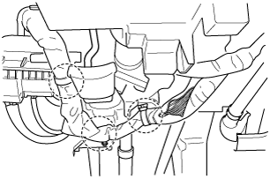
17. Detach the harness clips shown in the figure.
ac5wzw00001018
|
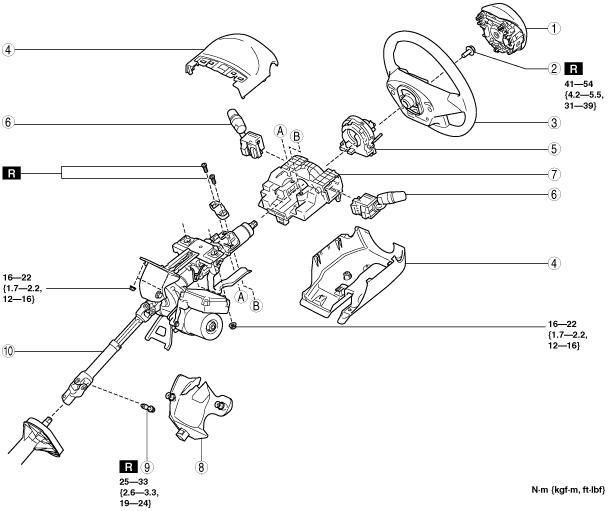
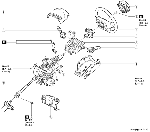
18. Remove in the order indicated in the table.
19. Install in the reverse order of removal.
20. If the EPS CM is replaced, perform the following procedure.
TypeA
ac5wzw00002493
|
|
1
|
Driver-side air bag module
|
|
2
|
Lockbolt
|
|
3
|
Steering wheel
(See Steering Wheel Removal Note.)
|
|
4
|
Column cover
|
|
5
|
Clock spring
|
|
6
|
Light switch, wiper and washer switch
|
|
7
|
Start stop unit
|
|
8
|
Joint cover
|
|
9
|
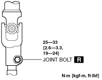
Joint bolt
|
|
10
|
Steering column component
|
ac5wzw00001569
|
|
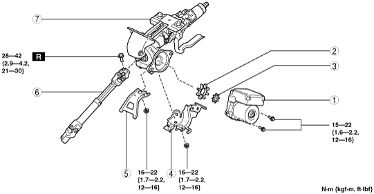
1
|
EPS CM
(See EPS CM Removal Note)
|
|
2
|
Rubber
|
|
3
|
Spacer
|
|
4
|
Harness bracket
|
|
5
|
Bracket (MTX vehicles)
(See Bracket Installation Note.)
|
|
6
|
Intermediate shaft
|
|
7
|
Steering column
|
Type B
ac5wzw00006954
|
|
1
|
Driver-side air bag module
|
|
2
|
Lockbolt
|
|
3
|
Steering wheel
(See Steering Wheel Removal Note.)
|
|
4
|
Column cover
|
|
5
|
Clock spring
|
|
6
|
Light switch, wiper and washer switch
|
|
7
|
Start stop unit
|
|
8
|
Joint cover
|
|
9
|
Joint bolt
|
|
10
|
Steering column component
|
ac5wzw00006989
|
|
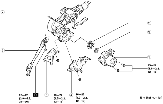
1
|
EPS CM
(See EPS CM Removal Note)
|
|
2
|
Rubber
|
|
3
|
Spacer
|
|
4
|
Harness bracket
|
|
5
|
Bracket (MTX vehicles)
(See Bracket Installation Note.)
|
|
6
|
Intermediate shaft
|
|
7
|
Steering column
|
Steering Wheel Removal Note
1. Set the vehicle wheels in the straight-ahead position.
2. Remove the steering wheel using any commercially available puller.
Steering Column Component Removal Note
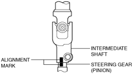
1. Lock the adjusting lever.
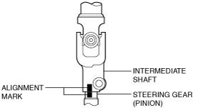
2. Place alignment marks on the steering gear (pinion) and the intermediate shaft as shown in the figure.
ac5wzw00006956
|
3. Remove the bolt, disconnect the intermediate shaft from the steering gear (pinion shaft).
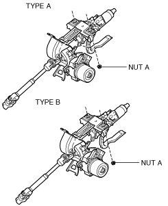
4. Remove nut A.
ac5wzw00006957
|
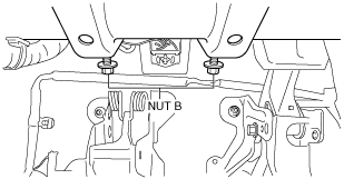
5. Loosen nut B.
ac5wzw00001022
|
6. Remove the steering column component by tilting it towards the loosened nut B and sliding it outward.
ac5wzw00001023
|
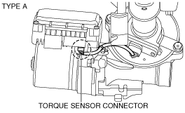
EPS CM Removal Note
1. Disconnect the torque sensor connector (EPS CM side).
ac5wzw00006990
|
ac5wzw00006991
|
2. Remove the EPS CM.
Bracket Installation Note
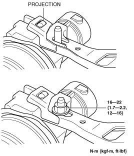
1. Insert the bracket bolt into the steering column and install the projecting part of the bracket to the installation area of the steering column.
ac5wzw00000333
|
2. Verify that the projection on the steering column is inserted into the hole in the bracket as shown in the figure and tighten the nut to the specified torque.
ac5wzw00001028
|
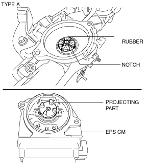
Spacer, Rubber and EPS CM Installation Note
1. Install the spacer and rubber to the steering column.
2. Install the EPS CM so that the projecting part of the EPS CM (rotor) is engaged with the notch in the rubber.
ac5wzw00006992
|
ac5wzw00006993
|
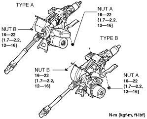
Steering Column Component Installation Note
1. Temporarily install nut B to the dashboard member.
ac5wzw00001022
|
2. Tilt the steering column component towards the temporarily installed nut B and temporarily install the steering column component to the instrument panel member using nut A
3. Tighten the nuts in the order of nut A and nut B.
ac5wzw00006958
|
4. Align the alignment marks on the steering column and the steering gear (pinion), which were placed before removing the intermediate shaft, and install the intermediate shaft.
ac5wzw00006959
|
ac5wzw00006960
|
Steering Wheel Installation Note
1. Set the vehicle wheels in the straight-ahead position, and install the steering wheel using a new lockbolt.