1. : Mazda SST number
2. : Global SST number
1: 49 UN30 3050
2: 303–050
Engine lifting bracket
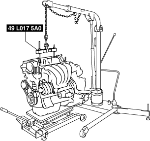
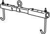
1: 49 L017 5A0
2: –
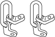
Support hanger
ENGINE DISASSEMBLY/ASSEMBLY [WITHOUT CYLINDER DEACTIVATION (SKYACTIV-G 2.0, SKYACTIV-G 2.5)]
id0110m1800500
Special Service Tool (SST)
|
1. : Mazda SST number
2. : Global SST number
|
|||
|
1: 49 UN30 3050
2: 303–050
Engine lifting bracket
|
|
1: 49 L017 5A0
2: –
Support hanger
|
|
Replacement Part
|
Gasket
Quantity: 1
Location of use: Oil filter body
|
Gasket
Quantity: 1
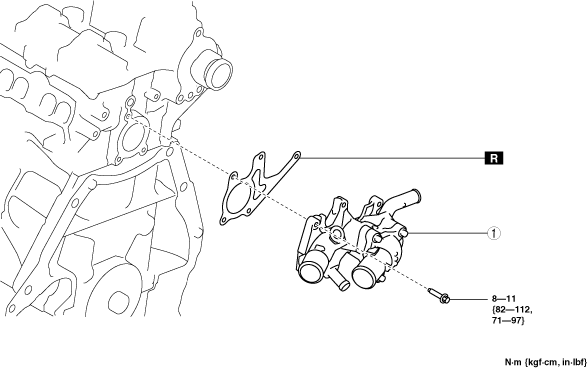
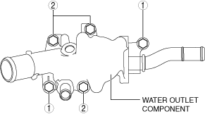
Location of use: Water outlet component
|
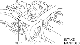
1. To enable to install the SST, disconnect the clip shown in the figure and set the wiring harness aside.
ac5uuw00006887
|
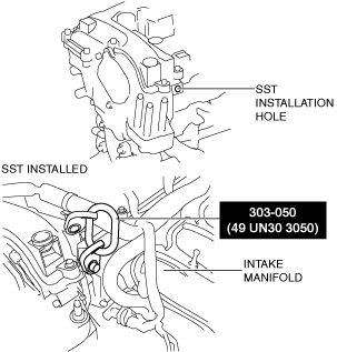
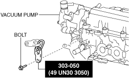
2. Install the SST using part number 99794 1025 or an M10 x 1.25, length 25 mm {0.98 in} bolt as shown in the figure.
Engine front side
am6zzw00011712
|
Engine rear side
ac5uuw00006888
|
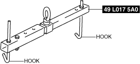
3. Engage the hooks of the SST (49 L017 5A0) to the SST (49 UN30 3050).
ac5uuw00006889
|
4. To ensure the safety of the work (control engine and transaxle sway), set a hoist as shown in the figure.
ac5uuw00006890
|
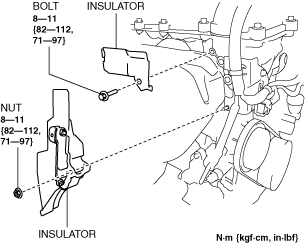
5. Remove the insulator shown in the figure.
ac5uuw00006891
|
6. Remove the exhaust system. (See EXHAUST SYSTEM REMOVAL/INSTALLATION [WITHOUT CYLINDER DEACTIVATION (SKYACTIV-G 2.0, SKYACTIV-G 2.5)].)
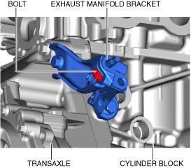
7. Remove the exhaust manifold bracket using the following procedure:
MTX
ac5uuw00006892
|
ATX
ac5uuw00006893
|
MTX
ac5uuw00006894
|
ATX
ac5uuw00006895
|
MTX
ac5uuw00006896
|
ATX
ac5uuw00006897
|
MTX
ac5uuw00006892
|
ATX
ac5uuw00006893
|
MTX
ac5uuw00006898
|
ATX
ac5uuw00006899
|
8. Remove the bracket No.1 (drive shaft bracket). (See FRONT DRIVE SHAFT REMOVAL/INSTALLATION.)
9. Remove the transfer bracket and transfer. (4WD) (See TRANSFER REMOVAL/INSTALLATION [FW6AX-EL].)
10. Remove the starter. (See STARTER REMOVAL/INSTALLATION [WITHOUT CYLINDER DEACTIVATION (SKYACTIV-G 2.0, SKYACTIV-G 2.5)].)
11. Remove the coolant control valve. (With coolant control valve) (See COOLANT CONTROL VALVE REMOVAL/INSTALLATION [WITHOUT CYLINDER DEACTIVATION (SKYACTIV-G 2.0, SKYACTIV-G 2.5)].)
12. Fix the drive plate using the crankshaft pulley lock bolt. (ATX)
13. Remove the torque converter installation nut from the starter installation hole. (See AUTOMATIC TRANSAXLE REMOVAL/INSTALLATION [FW6A-EL] (2WD).) (See AUTOMATIC TRANSAXLE REMOVAL/INSTALLATION [FW6AX-EL] (4WD).)
14. Disconnect the engine and transaxle, and lower only the engine from the engine lifter. (See MANUAL TRANSAXLE REMOVAL/INSTALLATION [C66M-R] (MTX, 2WD).) (See MANUAL TRANSAXLE REMOVAL/INSTALLATION [C66MX-R] (MTX, 4WD).) (See AUTOMATIC TRANSAXLE REMOVAL/INSTALLATION [FW6A-EL] (ATX, 2WD).) (See AUTOMATIC TRANSAXLE REMOVAL/INSTALLATION [FW6AX-EL] (ATX, 4WD).)
15. Remove the generator. (See GENERATOR REMOVAL/INSTALLATION [WITHOUT CYLINDER DEACTIVATION (SKYACTIV-G 2.0, SKYACTIV-G 2.5)].)
16. Remove the intake-air system. (See INTAKE-AIR SYSTEM REMOVAL/INSTALLATION [WITHOUT CYLINDER DEACTIVATION (SKYACTIV-G 2.0, SKYACTIV-G 2.5)].)
17. Remove the oil separator. (See POSITIVE CRANKCASE VENTILATION (PCV) VALVE REMOVAL/INSTALLATION [WITHOUT CYLINDER DEACTIVATION (SKYACTIV-G 2.0, SKYACTIV-G 2.5)].)
18. Remove the knock sensor (KS). (See KNOCK SENSOR (KS) REMOVAL/INSTALLATION [WITHOUT CYLINDER DEACTIVATION (SKYACTIV-G 2.0, SKYACTIV-G 2.5)].)
19. Remove the fuel injectors. (See FUEL INJECTOR REMOVAL/INSTALLATION [WITHOUT CYLINDER DEACTIVATION (SKYACTIV-G 2.0, SKYACTIV-G 2.5)].)
20. Remove the camshaft position (CMP) sensor. (See CAMSHAFT POSITION (CMP) SENSOR REMOVAL/INSTALLATION [WITHOUT CYLINDER DEACTIVATION (SKYACTIV-G 2.0, SKYACTIV-G 2.5)].)
21. Remove the vacuum pump. (See VACUUM PUMP REMOVAL/INSTALLATION [WITHOUT CYLINDER DEACTIVATION (SKYACTIV-G 2.0, SKYACTIV-G 2.5)].)
22. Remove the high pressure fuel pump and rear housing. (See HIGH PRESSURE FUEL PUMP REMOVAL/INSTALLATION [WITHOUT CYLINDER DEACTIVATION (SKYACTIV-G 2.0, SKYACTIV-G 2.5)].)
23. Remove the electric variable valve timing motor/driver. (See ELECTRIC VARIABLE VALVE TIMING MOTOR/DRIVER REMOVAL/INSTALLATION [WITHOUT CYLINDER DEACTIVATION (SKYACTIV-G 2.0, SKYACTIV-G 2.5)].)
24. Remove the oil filter. (See OIL FILTER REPLACEMENT [WITHOUT CYLINDER DEACTIVATION (SKYACTIV-G 2.0, SKYACTIV-G 2.5)].)
25. Remove the oil cooler. (If equipped) (See OIL COOLER REMOVAL/INSTALLATION [FW6A-EL, FW6AX-EL].)
26. Remove the engine oil solenoid valve. (See ENGINE OIL SOLENOID VALVE REMOVAL/INSTALLATION [WITHOUT CYLINDER DEACTIVATION (SKYACTIV-G 2.0, SKYACTIV-G 2.5)].)
27. Remove the engine oil temperature sensor/engine oil pressure sensor. (With coolant control valve) (See ENGINE OIL TEMPERATURE SENSOR/ENGINE OIL PRESSURE SENSOR REMOVAL/INSTALLATION [WITHOUT CYLINDER DEACTIVATION (SKYACTIV-G 2.0, SKYACTIV-G 2.5)].)
28. Remove the crankshaft position (CKP) sensor. (See CRANKSHAFT POSITION (CKP) SENSOR REMOVAL/INSTALLATION [WITHOUT CYLINDER DEACTIVATION (SKYACTIV-G 2.0, SKYACTIV-G 2.5)].)
29. Remove the dipstick.
30. Remove the ignition coil/ion sensors. (See IGNITION COIL/ION SENSOR REMOVAL/INSTALLATION [WITHOUT CYLINDER DEACTIVATION (SKYACTIV-G 2.0, SKYACTIV-G 2.5)].)
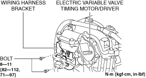
31. Remove the wiring harness bracket shown in the figure.
ac5uuw00006900
|
32. Remove the water pump drive belt. (See DRIVE BELT REMOVAL/INSTALLATION [WITHOUT CYLINDER DEACTIVATION (SKYACTIV-G 2.0, SKYACTIV-G 2.5)].)
33. Remove the following part. (See CYLINDER HEAD GASKET REPLACEMENT [WITHOUT CYLINDER DEACTIVATION (SKYACTIV-G 2.0, SKYACTIV-G 2.5)].)
34. Remove the water pump. (See WATER PUMP REMOVAL/INSTALLATION [WITHOUT CYLINDER DEACTIVATION (SKYACTIV-G 2.0, SKYACTIV-G 2.5)].)
35. Remove the clutch cover and clutch disc. (MTX) (See CLUTCH UNIT REMOVAL/INSTALLATION [C66M-R, C66MX-R].)
36. Remove the short cord of the engine oil level sensor. (if equipped) (See ENGINE OIL LEVEL SENSOR REMOVAL/INSTALLATION [WITHOUT CYLINDER DEACTIVATION (SKYACTIV-G 2.0, SKYACTIV-G 2.5)].)
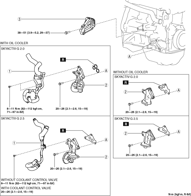
37. Remove in the order indicated in the table.
38. Assemble in the reverse order of disassembly.
Exhaust side
ac5wzw00012242
|
|
1
|
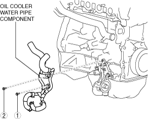
Oil cooler water pipe component (With oil cooler)
|
|
2
|
Oil filter body
(See Oil Filter Body Removal Note.)
|
|
3
|
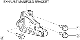
Exhaust manifold bracket (2WD)
|
Engine rear side
ac5uuw00005100
|
|
1
|
Water outlet component (Without coolant control valve)
|
Oil Filter Body Removal Note
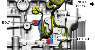
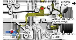
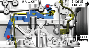
1. Remove the emission wiring harness using the following procedure.
SKYACTIV-G 2.0 (With coolant control valve and oil cooler)
ac5wzw00012243
|
SKYACTIV-G 2.5 (With coolant control valve, without oil cooler)
ac5wzw00012244
|
SKYACTIV-G 2.5 (With coolant control valve and oil cooler)
ac5wzw00012245
|
2. Remove the oil filter body.
Water Outlet Component Installation Note
1. Temporarily tighten the water outlet component installation bolts.
2. Tighten the bolts in the order shown in the figure.
ac5uuw00005101
|
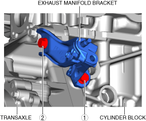
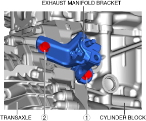
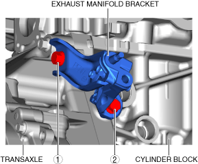
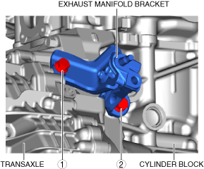
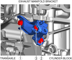
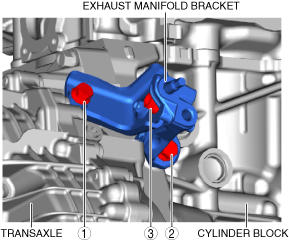
Exhaust Manifold Bracket Installation Note
1. Temporarily tighten the bolt (1) shown in the figure.
ac5uuw00006901
|
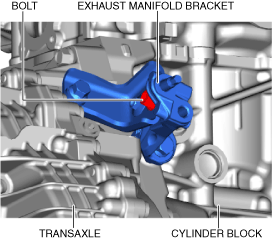
2. Temporarily tighten the bolt (2) shown in the figure.
3. Temporarily tighten the bolt (3) shown in the figure.
4. Tighten the bolt in the order shown in the figure.
Oil Filter Body Installation Note
1. After tightening the three bolts, tighten the first tightened bolt to the specified tightening torque again.
2. Install the emission wiring harness using the following procedure.
SKYACTIV-G 2.0 (With coolant control valve and oil cooler)
ac5wzw00012243
|
SKYACTIV-G 2.5 (With coolant control valve, without oil cooler)
ac5wzw00012244
|
SKYACTIV-G 2.5 (With coolant control valve and oil cooler)
ac5wzw00012245
|
Oil Cooler Water Pipe Component Installation Note (SKYACTIV-G 2.0)
1. Install the oil cooler water pipe component in the order shown in the figure.
ac5wzw00012246
|