|
1
|
INSPECT IG1 RELAY
• Switch the ignition off.
• Disconnect the negative battery terminal.
• Is the IG1 relay normal?
|
Yes
|
Go to the next step.
|
|
No
|
Replace the IG1relay, then go to Step 8.
|
|
2
|
INSPECT PCM DTC
• Perform the PCM DTC inspection using the M-MDS.
• Are any DTCs present?
|
Yes
|
Go to the applicable DTC inspection.
|
|
No
|
Go to the next step.
|
|
3
|
INSPECT BATTERY
• Is the battery normal?
|
Yes
|
Go to the next step.
|
|
No
|
Replace or charge the battery.
Then go to Step 8.
|
|
4
|
INSPECT GENERATOR
• Is the generator normal?
|
Yes
|
Go to the next step.
|
|
No
|
Replace the generator, then go to Step 8.
|
|
5
|
VERIFY SAS CONTROL MODULE CONNECTOR CONDITION
• Switch the ignition off.
• Disconnect the negative battery terminal and wait for 1 min or more.
• Remove the column cover.
• Disconnect the clock spring connector.
• Remove the glove compartment.
• Disconnect the passenger-side air bag module connector.
• Disconnect the driver and passenger-side front seat connectors.
• Remove the B-pillar lower trim.
• Disconnect the driver and passenger-side pre-tensioner seat belt connectors.
• Disconnect the driver and passenger-side curtain air bag module connectors.
• Disconnect the all SAS control module connectors.
• Inspect the connector and terminals (corrosion, damage, pin disconnection).
• Are the connector and terminals normal?
|
Yes
|
Go to the next step.
|
|
No
|
Replace the air bag harness.
After repair procedure, go to Step 8.
|
|
6
|
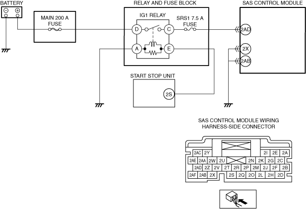
INSPECT SAS CONTROL MODULE POWER SUPPLY VOLTAGE
• SAS control module connectors are disconnected.
• Connect the negative battery terminal.
• Switch the ignition on (engine off or on).
• Measure the voltage at the following terminal (wiring harness-side):
-
― SAS control module terminal 2AD
• Is the voltage 8.1—15.9?
|
Yes
|
Go to the next step.
|
|
No
|
Inspect the SRS1 7.5 A fuse and MAIN 200 A fuse.
• If the fuse is blown:
-
― Refer to the wiring diagram and verify whether or not there is a common connector between MAIN 200 A fuse and SAS control module terminal 2AD.
If there is a common connector:
-
• Determine the malfunctioning part by inspecting the common connector and the terminal for corrosion, damage, or pin disconnection, and the common wiring harness for a short to ground.
• Repair or replace the malfunctioning part.
If there is no common connector:
-
• Repair or replace the wiring harness which has a short to ground.
-
― Replace the fuse.
• If the fuse is damaged:
-
― Replace the fuse.
• If the fuse is normal:
-
― Refer to the wiring diagram and verify whether or not there is a common connector between battery positive terminal and SAS control module terminal 2AD.
If there is a common connector:
-
• Determine the malfunctioning part by inspecting the common connector and the terminal for corrosion, damage, or pin disconnection, and the common wiring harness for an open circuit.
• Repair or replace the malfunctioning part.
If there is no common connector:
-
• Repair or replace the wiring harness which has an open circuit.
Go to Step 8.
|
|
7
|
INSPECT SAS CONTROL MODULE BODY GROUND CIRCUIT FOR OPEN CIRCUIT
• SAS control module connectors are disconnected.
• Switch the ignition off.
• Disconnect the negative battery terminal and wait 1 min or more.
• Inspect for continuity between the following terminals (wiring harness-side) and body ground:
-
― SAS control module terminal 2X
― SAS control module terminal 2AB
-
Note
-
• Inspect for continuity while shaking the wiring harness between the SAS control module and body ground.
• Is there continuity?
|
Yes
|
Go to the next step.
|
|
No
|
Refer to the wiring diagram and verify whether or not there is a common connector between SAS control module terminal and body ground.
If there is a common connector:
• Determine the malfunctioning part by inspecting the common connector and the terminal for corrosion, damage, or pin disconnection, and the common wiring harness for an open circuit.
• Replace the malfunctioning part.
If there is no common connector:
• Replace the wiring harness which has an open circuit.
Go to the next step.
|
|
8
|
PERFORM SAS CONTROL MODULE DTC INSPECTION
• Connect the SAS control module connectors.
• Reconnect all disconnected connectors.
• Connect the negative battery terminal.
• Switch the ignition ON (engine off or on).
• Clear the DTC for the SAS control module using the M-MDS.
• Perform the DTC inspection for the SAS control module using the M-MDS.
• Are the same DTCs present?
|
Yes
|
Repeat the inspection from Step 1.
• If the malfunction recurs, replace the SAS control module.
|
|
No
|
DTC troubleshooting completed.
|