POWER METAL OXIDE SEMICONDUCTOR FIELD EFFECT TRANSISTOR (POWER MOS FET) INSPECTION


id071100030300

1.  Disconnect the negative battery terminal. (See NEGATIVE BATTERY TERMINAL DISCONNECTION/CONNECTION.)

2.  Remove the following parts:

(1)  Console side panel (See CONSOLE SIDE PANEL REMOVAL/INSTALLATION.)
(2)  Selector lever knob (See SELECTOR LEVER COMPONENT REMOVAL/INSTALLATION.)
(3)  Shift panel (See SHIFT PANEL REMOVAL/INSTALLATION.)
(4)  Front console box (See FRONT CONSOLE BOX REMOVAL/INSTALLATION.)
(5)  Side wall (See SIDE WALL REMOVAL/INSTALLATION.)
(6)  Rear console panel (See REAR CONSOLE PANEL REMOVAL/INSTALLATION.)
(7)  Rear cooler duct (See REAR COOLER DUCT REMOVAL/INSTALLATION.)
(8)  Rear console (See REAR CONSOLE REMOVAL/INSTALLATION.)
(9)  Selector lever component (See SELECTOR LEVER COMPONENT REMOVAL/INSTALLATION.)
(10)  Selector lever bracket (See SELECTOR LEVER COMPONENT REMOVAL/INSTALLATION.)

3.  Remove the power MOS FET. (See POWER METAL OXIDE SEMICONDUCTOR FIELD EFFECT TRANSISTOR (POWER MOS FET) REMOVAL/INSTALLATION.)

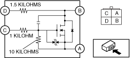
4.  Verify that the continuity between the power MOS FET terminals is as indicated in the table.

ac9wzw00005018

•  If there is any malfunction, replace the power MOS FET. (See POWER METAL OXIDE SEMICONDUCTOR FIELD EFFECT TRANSISTOR (POWER MOS FET) REMOVAL/INSTALLATION.)
•  If the blower motor operation is not normal even though no malfunction can be verified, inspect the rear climate control unit and related wiring harness. (See REAR CLIMATE CONTROL UNIT INSPECTION.)

Tester lead

Resistance (kilohm)

+

-

A
B
A
C
11
A
D
B
A
Continuity detected
B
C
Continuity detected
B
D
1.5
C
A
11
C
B
C
D
D
A
Continuity detected
D
B
1.5
D
C
Continuity detected