ENGINE CONTROL SYSTEM OPERATION INSPECTION [MZI-3.7]
id0103d2803700
Input Signal System Inspection Procedure
1. Find an irregular signal. (See Finding irregular signals.)
2. Locate source. (See Locating the source of unusual signals.)
3. Repair or replace the malfunctioning part.
4. Confirm that the irregular signal is no longer detected.
Finding irregular signals
-
1. Start the engine and idle the vehicle. You can assume that any signals that are out of specification by a wide margin are irregular.
2. When recreating the problem, any sudden change in monitor input signals that is not intentionally created by the driver can be determined as irregular.
Locating the source of unusual signals
-
Caution
-
• Compare the M-MDS monitor voltage with the measurement voltage using the digital measurement system function. If you use another tester, misreading may occur.
• When measuring voltage, attach the tester GND to the GND of the PCM that is being tested, or to the engine itself. If this is not performed, the measured voltage and actual voltage may differ.
• After connecting the pin to a waterproof coupler, confirming continuity and measuring the voltage, inspect the waterproof connector for cracks. If there are any, use sealant to fix them. Failure to do this may result in deterioration of the wiring harness or terminal from water damage, leading to problems with the vehicle.
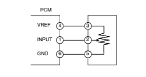
Variable resistance type 1 (TP sensor)
Input signal system inspection for variable resistance type 1
1. When an irregular signal is detected, measure the #1 PCM terminal voltage.
-
• If the #1 terminal voltage and the M-MDS monitor voltage are the same, proceed to the next step.
• If there is a difference of 0.5 V or more, inspect for the following points concerning the PCM connector:
-
― Female terminal opening is loose.
― Coupler (pin holder) damage
― Pin discoloration (blackness)
― Harness/pin crimp is loose or disconnected.
2. Measure the #2 sensor terminal voltage.
-
• If there is a 0.5 V or more difference between sensor and M-MDS voltages, inspect the wiring harness for open or short circuits.
• If the sensor and the M-MDS voltages are the same, inspect for the following points concerning the sensor connector:
-
― Female terminal opening is loose.
― Coupler (pin holder) damage
― Pin discoloration (blackness)
• If there are no problems, proceed to next investigation below.
Standard power supply system inspection for variable resistance type 1
-
• Confirm that the #3 terminal is at 5 V.
-
― If the measured voltage on the #3 terminal is 5 V, inspect the following points on the sensor connector.
― If there is no problem, inspect for the following:
-
• Female terminal opening is loose.
• Coupler (pin holder) damage
• Pin discoloration (blackness)
― If the #3 terminal measures other than 5 V, inspect for the following:
-
• Open or short circuit in wiring harness
• Harness/pin crimp is loose or disconnected.
GND system inspection for variable resistance type 1
-
• Confirm that terminal sensor #5 is at 0 V.
-
― If it is at 0 V, inspect the sensor.
-
• If necessary, replace the sensor.
― If not, inspect for the following:
-
• Open or short circuit in wiring harness
• Female terminal opening is loose causing an open or short circuit in wiring harness
• Coupler (pin holder) damage
• Pin discoloration (blackness)
• Harness/pin crimp is loose or disconnected.
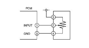
Variable resistance type 2 (MAF sensor and VSS)
GND system inspection for variable resistance type 2
-
• Confirm that terminal sensor #4 is at 0 V.
-
― If it is at 0 V, inspect the sensor.
-
• If necessary, replace the sensor.
― If not at 0 V, inspect for the following:
-
• Open circuit in wiring harness
• Female terminal opening is loose.
• Coupler (pin holder) damage
• Pin discoloration (blackness)
• Harness/pin crimp is loose or disconnected.
Input signal system inspection for variable resistance type 2
1. When an irregular signal is detected, measure the #1 PCM terminal voltage.
-
• If the #1 terminal voltage and the M-MDS monitor voltage are the same, proceed to the next step.
• If there is a difference of 0.5 V or more, inspect for the following points concerning the PCM connector:
-
― Female terminal opening is loose.
― Coupler (pin holder) damage
― Pin discoloration (blackness)
― Harness/pin crimp is loose or disconnected.
2. Measure the #2 sensor terminal voltage.
-
• If there is a 0.5 V or more difference between sensor and M-MDS voltages, inspect the wiring harness for open or short circuits.
• If the sensor and the M-MDS voltages are the same, inspect the following points concerning the sensor connector:
-
― Female terminal opening is loose.
― Coupler (pin holder) damage
― Pin discoloration (blackness)
― Harness/pin crimp is loose or disconnected.
• If there are no problems, proceed to next investigation below.
Electrical supply system inspection for variable resistance type 2
-
• Confirm that the sensor #3 terminal is B+.
-
― If the measured voltage on the #3 terminal is B+, inspect the following points on the sensor connector.
― If there is no problem, inspect for the following:
-
• Female terminal opening is loose.
• Coupler (pin holder) damage
• Pin discoloration (blackness)
― If the #3 terminal measures other than B+, inspect the following:
-
• Open or short circuit in wiring harness
• Harness/pin crimp is loose or disconnected.
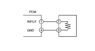
Thermistor type (IAT sensor and CHT sensor)
Input signal system inspection for thermistor type
1. When an irregular signal is detected, measure the #1 PCM terminal voltage.
-
• If the #1 terminal voltage and the M-MDS monitor voltage are the same, proceed to the next step.
• If there is a difference of 0.5 V or more, inspect the following points concerning the PCM connector:
-
― Female terminal opening loose
― Coupler (pin holder) damage
― Pin discoloration (blackness)
― Harness/pin crimp is loose or disconnected.
2. Measure the #2 sensor terminal voltage.
-
• If there is a 0.5 V or more difference between sensor and M-MDS voltages, inspect the wiring harness for open or short circuits.
• If the sensor and the M-MDS voltages are the same, inspect the following points concerning the sensor connector:
-
― Female terminal opening is loose.
― Coupler (pin holder) damage
― Pin discoloration (blackness)
― Harness/pin crimp is loose or disconnected.
• If there are no problems, proceed to next investigation below.
GND system inspection for thermistor type
-
• Confirm that terminal sensor #3 is at 0 V.
-
― If it is at 0 V, inspect the sensor. If necessary, replace the sensor.
― If not, inspect for the following:
-
• Open circuit in wiring harness
• Female terminal opening is loose.
• Coupler (pin holder) damage
• Pin discoloration (blackness)
• Harness/pin crimp is loose or disconnected.
Main Relay No.1 Operation Inspection
1. Verify that the main relay clicks when the ignition switch is turned to ON and off position.
-
• If there is no operation sound, inspect the following:
-
― Harness and connector between battery and main relay No.1 terminal E
― Harness and connector between PCM terminal 1BM and main relay No.1 terminal A (PCM connector (2 types))
― Harness and connector between PCM terminal 1AZ and main relay No.1 terminal A (PCM connector (3 types))
Drive-by-Wire Control System Inspection
Engine coolant temperature compensation inspection
1. Connect the M-MDS to the DLC-2.
2. Access the following PCM PIDs: (See ON-BOARD DIAGNOSTIC TEST [MZI-3.7 (PCM CONNECTOR (2 TYPES))].) (See ON-BOARD DIAGNOSTIC TEST [MZI-3.7 (PCM CONNECTOR (3 TYPES))].)
-
• ECT
• IAT
• RPM
3. Verify that the engine is cold, then start the engine.
4. Verify that the engine speed decreases as the engine warms up.
-
• If the engine speed does not decrease or decreases slowly, inspect the following:
-
Load compensation inspection
1. Start the engine and idle it.
2. Connect the M-MDS to the DLC-2.
3. Verify that the following DTC is not displayed: (See ON-BOARD DIAGNOSTIC TEST [MZI-3.7 (PCM CONNECTOR (2 TYPES))].) (See ON-BOARD DIAGNOSTIC TEST [MZI-3.7 (PCM CONNECTOR (3 TYPES))].)
-
• P0506, P0507 (PCM connector (2 types))
• P0506:00, P0507:00 (PCM connector (3 types))
-
4. Access the PCM PID RPM. (See ON-BOARD DIAGNOSTIC TEST [MZI-3.7 (PCM CONNECTOR (2 TYPES))].) (See ON-BOARD DIAGNOSTIC TEST [MZI-3.7 (PCM CONNECTOR (3 TYPES))].)
-
Note
-
• Excludes temporary idle speed drop just after the loads are turned on.
5. Verify that the engine speed is within the specification under each load condition.
-
• If load condition is not as specified, inspect the following:
-
Throttle position (TP) sweep inspection
1. Connect the M-MDS to the DLC-2.
2. Turn the ignition switch to the ON position.
3. Verify that none of the following DTC are displayed: (See ON-BOARD DIAGNOSTIC TEST [MZI-3.7 (PCM CONNECTOR (2 TYPES))].) (See ON-BOARD DIAGNOSTIC TEST [MZI-3.7 (PCM CONNECTOR (3 TYPES))].)
-
• P0122, P0123, P0222, P0223, P2101, P2107, P2112, P2122, P2123, P2127, P2128, P2135 (PCM connector (2 types))
• P0122:00, P0123:00, P0222:00, P0223:00, P2101:00, P2107:00, P2112:00, P2122:00, P2123:00, P2127:00, P2128:00, P2135:00 (PCM connector (3 types))
-
4. Access the PCM PIDs TP1, TP2. (See ON-BOARD DIAGNOSTIC TEST [MZI-3.7 (PCM CONNECTOR (2 TYPES))].) (See ON-BOARD DIAGNOSTIC TEST [MZI-3.7 (PCM CONNECTOR (3 TYPES))].)
5. Verify that the PID reading is within the CTP value. (See PCM INSPECTION [MZI-3.7].)
-
• If the PID reading is out of range, perform the following:
-
― Remove the air duct from the throttle body.
― Verify that the throttle valve opens when the accelerator pedal is depressed.
-
• If the throttle valve does not open, inspect the throttle valve actuator control motor and related wiring harness.
6. Gradually depress the throttle pedal and verify that the PID reading increases accordingly.
-
• If the PID reading drops momentarily, inspect the following:
-
7. Fully depress the throttle pedal and verify that the PID reading is within WOT value. (See PCM INSPECTION [MZI-3.7].)
-
• If the PID reading is out of range, perform the followings:
-
― Remove the air duct from throttle body.
― Verify that the throttle valve opens when throttle pedal is depressed.
-
• If the throttle valve does not open, inspect the throttle valve actuator control motor and related wiring harness.
Brake override system operation inspection
-
Note
-
• If the brake override system operates normally after performing the following inspection, the PCM detects DTC P2299:00.
1. Start the engine and run it is idling.
2. Verify that the engine speed becomes less than 1,100 rpm under the following conditions.
-
• P or N position
• Engine speed of 1,150 rpm or more other than idle
• Brake pedal depressed
-
― If the engine speed becomes less than 1,100 rpm, clear the PCM DTC using the M-MDS. (System operation is normal.)
― If the engine speed does not become less than 1,100 rpm, inspect for the following parts, then repair or replace the malfunctioning part:
-
Fuel Injector Operation Inspection
|
STEP
|
INSPECTION
|
RESULTS
|
ACTION
|
|
1
|
While cranking the engine, inspect for fuel injector operation sound at each cylinder using a soundscope.
Is the operation sound heard?
|
Yes
|
Fuel injector operation is normal.
|
|
No
|
All cylinders not heard:
• Go to the next step.
Some cylinders not heard:
• Go to Step 3.
|
|
2
|
Perform the main relay No.1 operation inspection.
Is the main relay No.1 operation normal?
|
Yes
|
Inspect the following:
• Fuel injector power system related wiring harness and connectors
• PCM connectors
• Fuel injector ground and related wiring harness and connectors
Repair or replace the malfunctioning part according to the inspection results.
|
|
No
|
Repair or replace the malfunctioning part according to the inspection results.
|
|
3
|
Switch the fuel injector connector of not operating fuel injector with operating fuel injector.
Is the operation sound heard?
|
Yes
|
Go to the next step.
|
|
No
|
Replace the fuel injector.
|
|
4
|
Are wiring harness and connectors of not operation fuel injector normal? (Open or short)
|
Yes
|
Inspect the PCM terminal voltage of fuel injector signal.
Repair or replace the malfunctioning part according to the inspection results.
|
|
No
|
Repair or replace the malfunctioning part according to the inspection results.
|
Fuel Cut Control System Inspection
-
Note
-
• This inspection has to perform after the Fuel Injector Operation Inspection.
If simulation function of the M-MDS is used:
1. Warm up the engine and idle it.
2. Connect the M-MDS to the DLC-2.
3. Access the PCM PIDs RPM and FUELSYS1. (See ON-BOARD DIAGNOSTIC TEST [MZI-3.7 (PCM CONNECTOR (2 TYPES))].) (See ON-BOARD DIAGNOSTIC TEST [MZI-3.7 (PCM CONNECTOR (3 TYPES))].)
4. Monitor the both PIDs while performing the following steps:
- (1) Depress the accelerator pedal and increase the RPM PID to 4,000 rpm.
- (2) Quickly release the accelerator pedal (brake pedal is not depressed) and verify that the FUELSYS1 PID is OL, and CL. when the RPM PID drops below 1,200 rpm.
-
-
• If not as specified, inspect the following:
-
If simulation function of the M-MDS is not used:
1. Warm up the engine and idle it.
2. Measure the fuel injector control signal wave profile using the oscilloscope while performing the following steps:
- (1) Depress the accelerator pedal and increase the engine speed to 4,000 rpm.
- (2) Quickly release the accelerator pedal (brake pedal is not depressed) and verify that the wave profile constant B+, and appears wave, when the engine speed drops below 2,200 rpm.
-
-
• If not as specified, inspect the following.
-
Fuel Pump Operation Inspection
1. Remove the fuel-filler cap.
2. Turn the ignition switch to the ON position.
3. Turn the fuel pump relay from off to on using the PCM PID FP and inspect if the operation sound is heard.
-
• If no operation sounds is heard, proceed to next step.
4. Measure the voltage at fuel pump terminal B (wiring harness-side).
-
Specification
-
• B+ (Ignition switch at on)
-
• If the voltage is as specified, inspect the following:
-
― Fuel pump continuity
― Fuel pump ground
• If not as specified, inspect the following:
-
― Wiring harness connector (Battery positive terminal—Fuel pump relay—Fuel pump)
― Wiring harness between fuel pump relay and PCM terminal 1V (PCM connector (2 types))
― Wiring harness between fuel pump relay and PCM terminal 1BI (PCM connector (3 types))
Fuel Pump Control System Inspection
1. Crank the engine and verify that fuel pump relay operation sound is heard.
2. If operation sound is not heard, inspect the following:
-
• Wiring harness and connectors (Ignition switch (IG1)—Fuel pump relay—PCM terminal 1V) (PCM connector (2 types))
• Wiring harness and connectors (Ignition switch (IG1)—Fuel pump relay—PCM terminal 1BI) (PCM connector (3 types))
Spark Test
1. Disconnect the fuel pump relay.
2. Verify that each ignition coil and connector is connected properly.
3. Inspect the ignition system in the following procedure:
-
Warning
-
• High voltage in the ignition system can cause strong electrical shock which can result in serious injury. Avoid direct contact to the vehicle body during the following spark test.
|
STEP
|
INSPECTION
|
ACTION
|
|
1
|
Disconnect the ignition coil from the spark plugs.
Remove the spark plugs.
• Ensure that the spark plugs don't have carbon deposits.
Are the spark plugs OK?
|
Yes
|
Go to the next step.
|
|
No
|
Perform 2 times of no-load racing at 4,000 rpm for 2 min to burn off the carbon deposits.
Repeat this step.
|
|
2
|
Inspect the spark plugs for damage, wear, and proper plug gap.
Are the spark plugs normal?
|
Yes
|
Go to the next step.
|
|
No
|
Replace the spark plugs, then go to the next step.
|
|
3
|
Reconnect the spark plugs to the ignition coil.
Ground the spark plugs to the engine.
Is a strong blue spark visible at each cylinder while cranking?
|
Yes
|
Ignition system is normal.
|
|
No
|
Some cylinders do not spark:
• Go to the next step.
All cylinders do not spark:
• Go to Step 5.
|
|
4
|
Inspect the following wiring harnesses for open or short:
• PCM connector (2 types):
-
― Ignition coil No.1 terminal C—PCM terminal 2A
― Ignition coil No.2 terminal C—PCM terminal 2F
― Ignition coil No.3 terminal C—PCM terminal 2K
― Ignition coil No.4 terminal C—PCM terminal 2W
― Ignition coil No.5 terminal C—PCM terminal 2AA
― Ignition coil No.6 terminal C—PCM terminal 2AE
• PCM connector (3 types):
-
― Ignition coil No.1 terminal C—PCM terminal 2BB
― Ignition coil No.2 terminal C—PCM terminal 2AT
― Ignition coil No.3 terminal C—PCM terminal 2B
― Ignition coil No.4 terminal C—PCM terminal 2AX
― Ignition coil No.5 terminal C—PCM terminal 2C
― Ignition coil No.6 terminal C—PCM terminal 2D
Are the wiring harnesses normal?
|
Yes
|
Inspect the ignition coil.
Repair or replace the malfunctioning part according to the inspection results.
|
|
No
|
Repair or replace suspected wiring harness and connector, then go to Step 1.
|
|
5
|
Turn the ignition switch to the ON position.
Measure the voltage at terminal A in each ignition coils.
Is the voltage B+?
|
Yes
|
Go to the next step.
|
|
No
|
Inspect the power supply circuit of ignition coils.
Repair or replace suspected wiring harness and connector.
|
|
6
|
Verify continuity between each ignition coils terminal B and battery negative terminal.
Is there continuity?
|
Yes
|
Go to the next step.
|
|
No
|
Inspect the ground circuit of ignition coils.
Repair or replace suspected wiring harness and connector.
|
|
7
|
Does the PCM connector or ignition coil connectors have poor connection?
|
Yes
|
Repair or replace the connector, then go to Step 1.
|
|
No
|
Go to the next step.
|
|
8
|
Are the CKP sensor and crankshaft pulley normal?
|
Yes
|
Inspect for open or short circuit in wiring harness and connector of CKP sensor.
Repair or replace suspected wiring harness and connector.
|
|
No
|
Repair or replace the malfunctioning part according to the inspection results, then go to Step 1.
|
Purge Control System Inspection
If simulation function of the M-MDS is used:
1. Start the engine.
2. Disconnect the vacuum hose between purge solenoid valve and charcoal canister.
3. Put the finger to the purge solenoid valve and verify that there is no vacuum applied when the engine is cold.
-
• If there is a vacuum, inspect the following:
-
― Wiring harness and connectors (Purge solenoid valve—PCM terminal 1BC) (PCM connector (2 types))
― Wiring harness and connectors (Purge solenoid valve—PCM terminal 2H) (PCM connector (3 types))
4. Connect the M-MDS to the DLC-2 and verify that the following DTC is shown: (See ON-BOARD DIAGNOSTIC TEST [MZI-3.7 (PCM CONNECTOR (2 TYPES))].) (See ON-BOARD DIAGNOSTIC TEST [MZI-3.7 (PCM CONNECTOR (3 TYPES))].)
-
• P0443 (PCM connector (2 types))
• P0443:00 (PCM connector (3 types))
-
5. Access the PCM PID EVAPCP. (See ON-BOARD DIAGNOSTIC TEST [MZI-3.7 (PCM CONNECTOR (2 TYPES))].) (See ON-BOARD DIAGNOSTIC TEST [MZI-3.7 (PCM CONNECTOR (3 TYPES))].)
6. Increase the duty value of the purge valve to 50 % and inspect if the operation sound of the valve is heard.
-
• If the operation sound is heard, inspect for the loose or damaged vacuum hose. (Intake manifold—Purge solenoid valve—Charcoal canister)
7. Warm up the engine to normal operating temperature.
-
Caution
-
• While performing Step 8 with vehicle driving, always operate the vehicle in a safe and lawful manner.
• When the M-MDS is used to observe monitor system status while driving, be sure to have another technician with you, or record the data in the M-MDS using the PID/DATA MONITOR AND RECORD capturing function and inspect later.
8. Monitor the EVAPCP PID using the M-MDS, and drive the vehicle approx. 2,000 rpm for 30 s or more.
-
• If the EVAPCP PID is 0 %, inspect the following PCM PIDs:
-
― MAF, APP1, APP2, APP3 (PCM connector (2 types)), TP_REL and LOAD
If simulation function of the M-MDS is not used:
1. Start the engine.
2. Disconnect the vacuum hose between purge solenoid valve and charcoal canister.
3. Put the finger to the purge solenoid valve and verify that there is no vacuum applied when the engine is cold.
-
• If there is a vacuum, inspect the following:
-
― Wiring harness and connectors (Purge solenoid valve—PCM terminal 1BC) (PCM connector (2 types))
― Wiring harness and connectors (Purge solenoid valve—PCM terminal 2H) (PCM connector (3 types))
4. Connect the M-MDS to the DLC-2 and verify that the following DTC is shown: (See ON-BOARD DIAGNOSTIC TEST [MZI-3.7 (PCM CONNECTOR (2 TYPES))].) (See ON-BOARD DIAGNOSTIC TEST [MZI-3.7 (PCM CONNECTOR (3 TYPES))].)
-
• P0443 (PCM connector (2 types))
• P0443:00 (PCM connector (3 types))
-
5. Access the PCM PIDs EVAPCP and ECT. (See ON-BOARD DIAGNOSTIC TEST [MZI-3.7 (PCM CONNECTOR (2 TYPES))].) (See ON-BOARD DIAGNOSTIC TEST [MZI-3.7 (PCM CONNECTOR (3 TYPES))].)
6. Verify that the ECT PID is more than 78 °C {172 °F}.
-
• If the ECT PID reading indicates less than 78 °C {172 °F}, perform the ECT inspection.
7. Set the vehicle on the dynamometer or chassis roller.
-
Warning
-
• When the dynamometer or chassis roller is operating, there is a possibility that the operator may come into contact with or be caught up in the rotating parts, leading to serious injuries or death. When performing work while the dynamometer or chassis roller is operating, be careful not to come into contact with or caught up in any of the rotating parts.
8. Drive the vehicle approx. 2,000 rpm for 30 s or more.
-
• If there is no vacuum, inspect the following:
-
― Wiring harness and connector (Main relay No.1—Purge solenoid valve—PCM terminal 1BC) (PCM connector (2 types))
― Wiring harness and connector (Main relay No.1—Purge solenoid valve—PCM terminal 2H) (PCM connector (3 types))
― PCM PIDs MAF, APP1, APP2, APP3 (PCM connector (2 types)), TP_REL and LOAD
-
• If there is vacuum, inspect the following:
-
― Vacuum hose (Purge solenoid valve—Charcoal canister)
A/C Cut-off Control System Inspection
1. Start the engine.
2. Turn the A/C switch and the fan switch on.
3. Verify that the A/C compressor magnetic clutch actuates.
-
4. Depress the accelerator pedal to WOT and verify that the magnetic clutch does not actuate for 2—5 s.
-
• If it actuates, inspect as follows:
-
― Open or short to ground circuit in wiring harness and connectors (A/C relay—PCM terminal 1N) (PCM connector (2 types))
― Open or short to ground circuit in wiring harness and connectors (A/C relay—PCM terminal 1W) (PCM connector (3 types))
― A/C related parts
― PCM PIDs APP1, APP2 and APP3 (PCM connector (2 types))
Cooling Fan Control System Inspection
1. Connect the M-MDS to the DLC-2.
2. Start the engine and warm it up to normal operating temperature.
3. Perform the KOER self test. (See KOEO/KOER SELF TEST [MZI-3.7 (PCM CONNECTOR (2 TYPES))].) (See KOEO/KOER SELF TEST [MZI-3.7 (PCM CONNECTOR (3 TYPES))].)
4. Verify the cooling fan operates during KOER self test.
-
Cooling fans do not operate
-
• Inspect for followings:
-
― PCM connector (2 types):
-
• Open circuit between cooling fan relay No.1 and PCM terminal 1V
• Open circuit between cooling fan relay No.2 and PCM terminal 1V
• Open or short circuit between fan control module No.1 terminal B and PCM terminal 1AM
• Open or short circuit between fan control module No.2 terminal B and PCM terminal 1AM
― PCM connector (3 types):
-
• Open circuit between cooling fan relay No.1 and PCM terminal 1BI
• Open circuit between cooling fan relay No.2 and PCM terminal 1BI
• Open or short circuit between fan control module No.1 terminal B and PCM terminal 1BR
• Open or short circuit between fan control module No.2 terminal B and PCM terminal 1BR
• If there is malfunction, repair or replace malfunctioning part.
-
Cooling fan motor No.1 does not operate
-
• Inspect for followings:
-
― Open or short to ground circuit between fan control module No.1 and cooling fan motor No.1
― Poor connection of the fan control module No.1 connector or cooling fan motor No.1 connector
― Open or short circuit between ignition switch (IG1) and cooling fan relay No.1
― Open circuit between cooling fan relay No.1 and battery positive terminal
― Open circuit between cooling fan relay No.1 and fan control module No.1 terminal A
― Open circuit between fan control module No.1 terminal C and ground
― Poor connection of the fan control module No.1 connector
• If there is malfunction, repair or replace malfunctioning part.
-
Cooling fan motor No.2 does not operate
-
• Inspect for followings:
-
― Open or short to ground circuit between fan control module No.2 and cooling fan motor No.2
― Poor connection of the fan control module No.2 connector or cooling fan motor No.2 connector
― Open or short circuit between ignition switch (IG1) and cooling fan relay No.2
― Open circuit between cooling fan relay No.2 and battery positive terminal
― Open circuit between cooling fan relay No.2 and fan control module No.2 terminal A
― Open circuit between fan control module No.2 terminal C and ground
― Poor connection of the fan control module No.2 connector
• If there is malfunction, repair or replace malfunctioning part.
Variable Valve Timing Control System Operation Inspection
When idling cannot be continued
-
Note
-
1. Remove the OCV and verify that the spool valve is at maximum retard position.
-
2. Connect the OCV.
3. Turn the ignition switch to ON position.
4. Verify that the spool valve is at max. retard position.
-
• If the spool valve is stuck in advance direction, inspect the following:
-
― Short circuit in harnesses or connectors between OCV and PCM
5. Inspect the variable valve timing actuator.
When idling can be continued
For right bank
1. Disconnect OCV (RH) connector.
2. Warm up the engine and it at idle.
3. Apply the battery voltage to the OCV and verify that the engine idles roughly or stalls.
-
• If the engine idles roughly or stalls, inspect the timing belt component (valve timing deviation).
• If the engine does not idle roughly or stall, go to the next step.
4. Remove the OCV (RH) and perform spool valve operation inspection. (See OIL CONTROL VALVE (OCV) REMOVAL/INSTALLATION [MZI-3.7].)
-
• If not as specified, inspect the following:
-
― Harnesses and connectors between OCV (RH) and PCM have an open or short circuit.
• If as specified, inspect the following right bank hydraulic passages for clogging or leakage, or both:
-
― Oil pressure switch—OCV
― OCV—Camshaft
― Camshaft internal passage
5. If they are normal, replace the right bank camshaft pulley (with built-in variable valve timing actuator).
When idling can be continued
For left bank
1. Disconnect OCV (LH) connector.
2. Warm up the engine to idle.
3. Apply the battery voltage to the OCV and verify that the engine idles roughly or stalls.
-
• If the engine idles roughly or stalls, inspect the timing belt component (valve timing deviation).
• If the engine does not idle roughly or stall, go to the next step.
4. Remove the OCV (LH) and perform spool valve operation inspection. (See OIL CONTROL VALVE (OCV) REMOVAL/INSTALLATION [MZI-3.7].)
-
• If not as specified, inspect the following:
-
― Harnesses and connectors between OCV (LH) and PCM have an open or short circuit.
• If as specified, inspect the following left bank hydraulic passages for clogging or leakage or both:
-
― Oil pressure switch—OCV
― OCV—Camshaft
― Camshaft internal passage
5. If they are normal, replace the left bank camshaft pulley (with built-in variable valve timing actuator).