EV SYSTEM DOES NOT START


id300300000800

Warning
<<High voltage>>
•  If the necessary measures are not taken before servicing an electric vehicle, it could cause electrical shock and result in serious injury or, in the worst case, death. Before servicing the electric vehicle, refer to [HIGH VOLTAGE SERVICE CAUTIONS] in the general information and implement the necessary measures. (See HIGH VOLTAGE SERVICE CAUTIONS.)

Outline

Malfunction symptom

EV system does not start

Description
•  The EV system does not start even though the power switch is operated.
•  The power switch POWER indicator light does not turn on even when the main power is switched ON.
•  READY is not displayed in the instrument cluster after the EV system starts.
Possible cause
EV system start conditions are not met:
•  Power switch signal circuit malfunction (body control module (BCM) detects DTC)
―  Short to power supply in power switch signal circuit
―  Open circuit in power switch signal circuit
•  Power switch malfunction
•  The body control module (BCM) recognizes that the brake pedal is not depressed.
―  Brake switch malfunction
―  Malfunction in wiring harness between brake switch and body control module (BCM), or connectors
•  Body control module (BCM) recognizes that steering lock is not released
―  Steering lock unit malfunction
•  PCM and body control module (BCM) recognizes position other than P position
―  CAN communication error
―  Parking lock actuator malfunction
―  Selector lever malfunction
•  Body control module (BCM) malfunction
•  PCM cannot receive start request from body control module (BCM)
―  CAN communication error
•  Fail-safe due to PCM, drive motor control module or BECM DTC detection
―  EV system malfunction
―  High voltage battery voltage decreased
•  False recognition that charge connector is connected
―  Normal charge port connection detection circuit malfunction (battery charge control module detects DTC)
―  Quick charge port connection detection circuit (PCM detects DTC)
•  High voltage battery charging (normal operation)
Note
•  If the high voltage contactor does not activate, DTC P0AE3:00 is detected.
High voltage contactor cannot be driven:
•  Discharged lead-acid battery (See DISCHARGED LEAD-ACID BATTERY.)
•  Short circuit in power transistor of PTC internal high voltage circuit
Power switch POWER indicator light false illumination:
•  Power switch POWER indicator light control circuit malfunction
―  Short to power supply in power switch POWER indicator light control circuit
•  Body control module (BCM) malfunction
READY status incorrect display
•  Instrument cluster cannot receive main power status signal
―  CAN communication malfunction
•  Instrument cluster malfunction
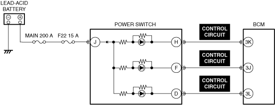
System wiring diagram
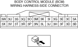
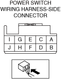
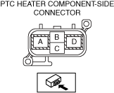
Connector diagram


Diagnostic Procedure

Warning
<<High voltage>>
•  If necessary measures such as wearing the correct protective gear are not taken when inspecting or removing/installing the high voltage parts, it could cause electrical shock and result in serious injury or, in the worst case, death.
•  Before inspecting or removing/installing the high voltage parts, refer to [HIGH VOLTAGE SERVICE CAUTIONS] in the general information and [High Voltage Part Inspection and Removal/Installation Notes] of the high voltage system service cautions and implement the necessary measures and preparations. (See HIGH VOLTAGE SERVICE CAUTIONS.) (See HIGH VOLTAGE SYSTEM SERVICE CAUTIONS.)

Step

Inspection

Results

Action

1
VERIFY EV SYSTEM RELATED DTCs
•  Perform the DTC inspections for the following modules.
―  PCM
―  BECM
―  Battery charge control module
―  Drive motor control module
―  Body control module (BCM)
―  Selector lever
―  Parking lock actuator
•  Is a DTC displayed?
Yes
Repair the malfunctioning location according to the applicable DTC troubleshooting.
No
Go to the next step.
2
INSPECT LEAD-ACID BATTERY FOR MALFUNCTION
•  Inspect the applicable part.
•  Is the part normal?
Yes
Go to the next step.
No
Repair or replace the malfunctioning location and perform the repair completion verification.
3
VERIFY PUSH BUTTON START SYSTEM OPERATION
•  Perform the troubleshooting procedure according to the symptom troubleshooting for [PUSH BUTTON START SYSTEM DOES NOT OPERATE] of the security and locks.
•  Is the troubleshooting result normal?
Yes
Go to the next step.
No
Repair or replace the malfunctioning location and perform the repair completion verification.
4
INSPECT POWER SWITCH INDICATOR FOR MALFUNCTION
•  Inspect the applicable part.
•  Is the part normal?
Yes
Go to the next step.
No
Repair or replace the malfunctioning location and perform the repair completion verification.
5
INSPECT POWER SWITCH POWER INDICATOR LIGHT CONTROL CIRCUIT FOR SHORT TO POWER SUPPLY AND OPEN CIRCUIT
•  Inspect the applicable circuit for a short to power supply and open circuit.
•  Is the circuit normal?
Yes
Go to the next step.
No
Repair or replace the malfunctioning location and perform the repair completion verification.
6
INSPECT INSTRUMENT CLUSTER FOR MALFUNCTION
•  Inspect the applicable part.
•  Is the part normal?
Yes
Go to the next step.
No
Repair or replace the malfunctioning location and perform the repair completion verification.
7
INSPECT STEERING LOCK UNIT FOR MALFUNCTION
•  Inspect the applicable part.
•  Is the part normal?
Yes
Go to the next step.
No
Repair or replace the malfunctioning location and perform the repair completion verification.
8
INSPECT PTC HEATER FOR MALFUNCTION
Warning
<<High voltage>>
•  Wear insulating gloves when working on a high voltage system.
•  Disconnect the PTC heater high voltage cable connector.
Caution
•  Connect each probe of the circuit tester to the designated terminal. Resistance cannot be accurately measured if reversed.
•  Connect the circuit tester probes to the following terminals and measure the resistance between PTC heater terminals A and D.
―  Terminal A: + probe
―  Terminal D: - probe
•  Is the resistance 1.0 MΩ or more?
Yes
Explain to the customer that the EV system may not start under the following conditions.
•  High voltage battery charging
•  High voltage battery voltage decreased
Perform the repair completion verification.
No
Repair or replace the malfunctioning location and perform the repair completion verification.
Repair completion verification
VERIFY THAT VEHICLE IS REPAIRED
•  Install/connect the part removed/disconnected during the troubleshooting procedure.
•  Has the malfunction symptom been eliminated?
Yes
Complete the symptom troubleshooting. (Explain contents of repair to customer)
No
Refer to the CAN (controller area network) malfunction diagnosis flow to inspect for a CAN communication error.