 |
a30zzw00004058
MOUNT DISASSEMBLY/ASSEMBLY
id301000100200
No.1 mount
1. Remove front under cover No.2. (See FRONT UNDER COVER No.2 REMOVAL/INSTALLATION.)
2. Remove the gusset. (See FRONT CROSSMEMBER REMOVAL/INSTALLATION.)
3. Remove floor under cover No.1. (See FLOOR UNDER COVER REMOVAL/INSTALLATION.)
4. Remove using the procedure shown in the figure.
5. Install in the reverse order of removal.
a30zzw00004058
|
|
1
|
No.1 mount bracket
(See No.1 Mount Removal Note.)
(See No.1 Mount Installation Note.)
|
|
2
|
No.1 mount rubber
(See No.1 Mount Installation Note.)
|
No.1 Mount Removal Note
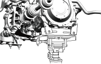
1. Support the electric motor on a jack.
a30zzw00005459
|
a30zzw00004061
|
No.1 Mount Installation Note
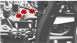
1. Temporarily tighten the bolts shown in the figure.
a30zzw00004062
|
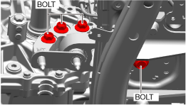
2. Tighten the bolts shown in the figure.
a30zzw00004063
|
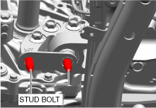
3. Tighten the stud bolts.
a30zzw00004061
|
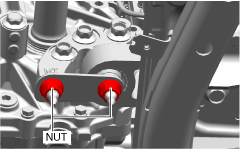
4. Temporarily tighten the nuts shown in the figure.
a30zzw00004064
|
5. Tighten the nuts shown in the figure.
a30zzw00004064
|
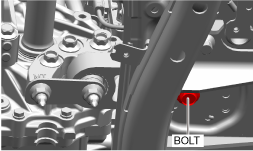
6. Tighten the bolt shown in the figure.
a30zzw00004065
|
No.3 mount
Replacement part
|
Clip
Quantity: 3
Location of use: electric motor insulator
|
High Voltage Part Inspection And Removal/Installation Notes
1. Verify that the READY indicator on the instrument cluster is not illuminated.
2. Disconnect the negative lead-acid battery terminal. (See NEGATIVE LEAD-ACID BATTERY TERMINAL DISCONNECTION/CONNECTION.)
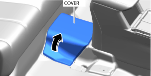
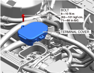
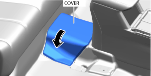
3. Partially peel back the cover.
a30zzw00004019
|
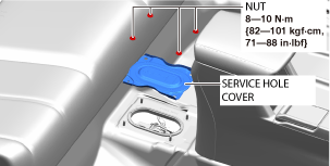
4. Remove the service hole cover.
a30zzw00004020
|
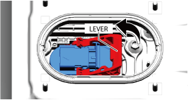
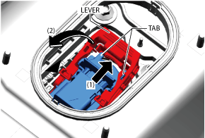
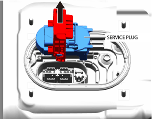
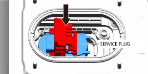
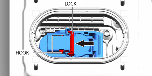
5. Wear insulating gloves and remove the service plug using the following procedure.
a30zzw00004021
|
a30zzw00004502
|
a30zzw00004503
|
a30zzw00004023
|
6. After removing the service plug, leave it for 10 min.
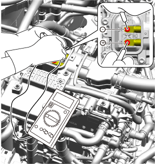
7. Wear insulating gloves and measure the voltage at the high voltage cable connection (junction box No.3 side) using the following procedure.
a30zzw00004024
|
a30zzw00006968
|
a30zzw00004025
|
a30zzw00006968
|
8. Remove the coolant reserve tank with the hose still connected to it, and secure it using rope or other means so that it does not interfere with work. (See COOLANT RESERVE TANK REMOVAL/INSTALLATION.)
9. Remove the DC-DC converter with the hose and wiring harness still connected to it, and secure it using rope or other means so that it does not interfere with work. (See DC-DC CONVERTER REMOVAL/INSTALLATION.)
10. Disconnect the high voltage cable (junction box No.3 side). (See HIGH VOLTAGE CABLE REMOVAL/INSTALLATION.)
11. Remove junction box No.3. (See JUNCTION BOX No.3 REMOVAL/INSTALLATION.)
12. Remove front under cover No.2. (See FRONT UNDER COVER No.2 REMOVAL/INSTALLATION.)
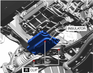
13. Remove the clips, then remove the insulator shown in the figure.
a30zzw00004515
|
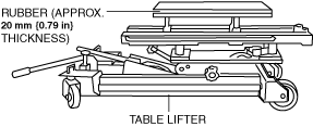
14. Use a commercially available table lifter to support the electric motor.
a30zzw00006812
|
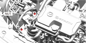
15. Remove the nuts shown in the figure and remove the accumulator together with the bracket. (See ACCUMULATOR REMOVAL/INSTALLATION.)
a30zzw00004066
|
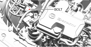
16. Remove the bolt shown in the figure and remove the heat pump unit No.2 bracket. (See HEAT PUMP CONTROL UNIT REMOVAL/INSTALLATION [FULL-AUTO AIR CONDITIONER].)
a30zzw00004067
|
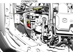
17. Disconnect the connector shown in the figure.
a30zzw00004081
|
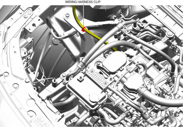
18. Detach the wiring harness clip shown in the figure.
a30zzw00004068
|
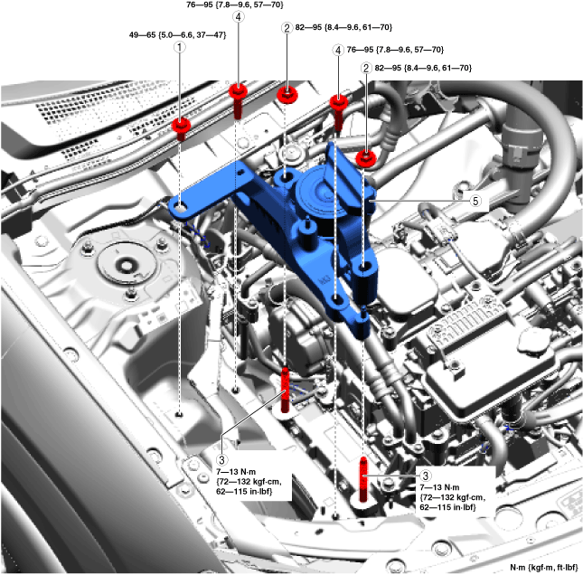
19. Remove using the procedure shown in the figure.
20. Install in the reverse order of removal.
a30zzw00004516
|
|
1
|
Bolt
|
|
2
|
Nut
(See No.3 Mount Removal Note.)
(See No.3 Mount Installation Note.)
|
|
3
|
Stud bolt
(See No.3 Mount Installation Note.)
|
|
4
|
Bolt
(See No.3 Mount Removal Note.)
(See No.3 Mount Installation Note.)
|
|
5
|
No.3 mount
(See No.3 Mount Removal Note.)
(See No.3 Mount Installation Note.)
|
21. Wear insulating gloves and install the service plug using the following procedure.
a30zzw00004026
|
a30zzw00004027
|
a30zzw00004028
|
22. Install the service hole cover.
a30zzw00004020
|
23. Close the cover.
a30zzw00004029
|
24. Connect the negative lead-acid battery terminal. (See NEGATIVE LEAD-ACID BATTERY TERMINAL DISCONNECTION/CONNECTION.)
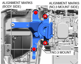
No.3 Mount Removal Note
1. Place alignment marks at the positions shown in the figure so that they can be assembled to the same positions as before removal.
a30zzw00004652
|
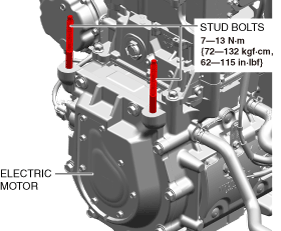
No.3 Mount Installation Note
1. Tighten the electric motor stud bolts.
a30zzw00004970
|
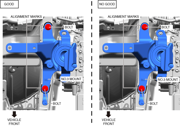
2. Align the alignment marks on the body side with the No.3 mount, and temporarily tighten the bolts shown in the figure.
a30zzw00004653
|
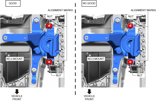
3. Temporarily tighten the nuts shown in the figure while aligning the alignment marks of the No.3 mount with the nuts.
a30zzw00004654
|
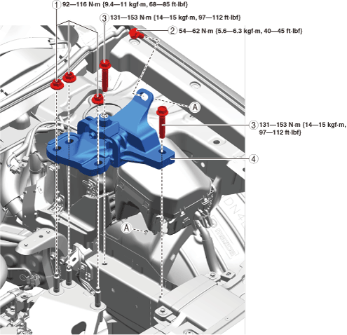
4. Tighten the No.3 mount installation bolts and nuts in the order shown in the figure.
a30zzw00004655
|
5. Remove the table lifter or garage jack.
No.4 mount
Replacement part
|
Clip
Quantity: 3
Location of use: electric motor insulator
|
1. Remove the lead-acid battery and battery tray. (See LEAD-ACID BATTERY REMOVAL/INSTALLATION.)
2. Remove front under cover No.2. (See FRONT UNDER COVER No.2 REMOVAL/INSTALLATION.)
3. Remove the clips, then remove the insulator shown in the figure.
a30zzw00004515
|
4. Use a commercially available table lifter to support the electric motor.
a30zzw00006812
|
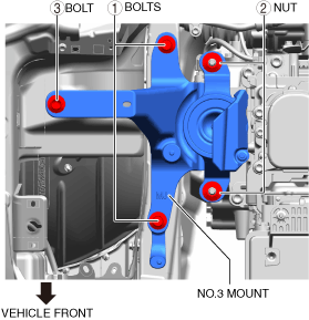
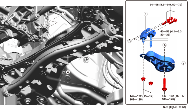
5. Remove using the procedure shown in the figure.
6. Install in the reverse order of removal.
a30zzw00004075
|
|
1
|
Nut
(See No.4 Mount Removal Note.)
(See No.4 Mount Installation Note.)
|
|
2
|
Bolts
|
|
3
|
Bolts
(See No.4 Mount Removal Note.)
(See No.4 Mount Installation Note.)
|
|
4
|
No.4 mount
(See No.4 Mount Removal Note.)
(See No.4 Mount Installation Note.)
|
No.4 Mount Removal Note
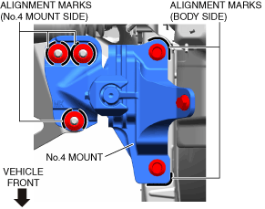
1. Place alignment marks at the positions shown in the figure so that they can be assembled to the same positions as before removal.
a30zzw00004974
|
2. Remove the No.4 mounts.
No.4 Mount Installation Note
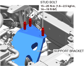
1. Tighten the support bracket stud bolts.
a30zzw00004077
|
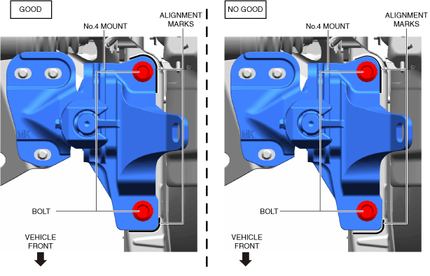
2. Align the alignment marks on the body side with the No.4 mount, and temporarily tighten the bolts shown in the figure.
a30zzw00004078
|
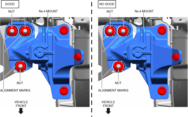
3. Temporarily tighten the nuts shown in the figure while aligning the alignment marks of the No.4 mount with the nuts.
a30zzw00004079
|
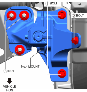
4. Tighten the No.4 mount installation bolts and nuts in the order shown in the figure.
a30zzw00004080
|
5. Remove the table lifter or garage jack.