AIR MIX ACTUATOR INSTALLATION
id074000705700
Driver-side
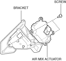
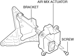
1. Install the air mix actuator to the bracket.
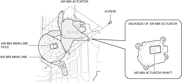
2. Install the screws.
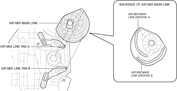
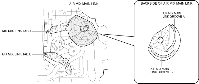
3. Align the following air mix link tabs with the air mix main link grooves and install the air mix main link.
-
― Air mix link tab A and air mix main link groove A
― Air mix link tab B and air mix main link groove B
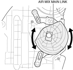
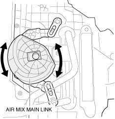
4. Move the air mix main link in the direction shown in the figure and verify that it rotates smoothly.
-
Note
-
• The air mix main link is not secured, therefore hold it with your hand so that it does not detach.
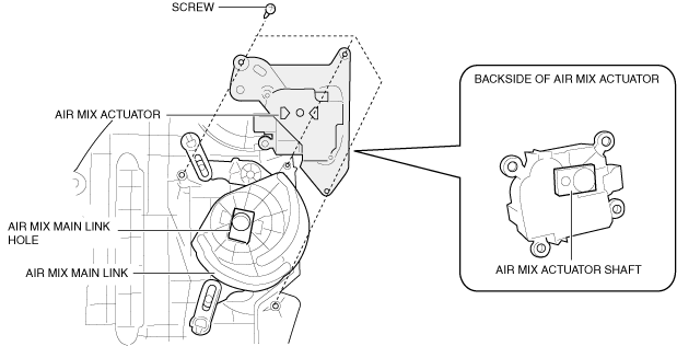
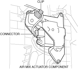
5. Align the air mix main link hole with the shape of the air mix actuator shaft, and install the air mix actuator.
6. Install the screws.
7. Install the clip.
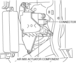
8. Connect the connector.
9. Connect the negative battery terminal. (See NEGATIVE BATTERY TERMINAL DISCONNECTION/CONNECTION.)
Passenger-side
1. Install the air mix actuator to the bracket.
2. Install the screws.
3. Align the following air mix link tabs with the air mix main link grooves and install the air mix main link.
-
― Air mix link tab A and air mix main link groove A
― Air mix link tab B and air mix main link groove B
4. Move the air mix main link in the direction shown in the figure and verify that it rotates smoothly.
-
Note
-
• The air mix main link is not secured, therefore hold it with your hand so that it does not detach.
5. Align the air mix main link hole with the shape of the air mix actuator shaft, and install the air mix actuator.
6. Install the screws.
7. Connect the connector.
8. Install the following parts:
- (1) Passenger-side front heat duct No.1 (See FRONT HEAT DUCT REMOVAL/INSTALLATION.)
-
- (2) Center lower panel (See CENTER LOWER PANEL REMOVAL/INSTALLATION.)
-
- (3) Knee air bag module (See KNEE AIR BAG MODULE REMOVAL/INSTALLATION [TWO-STEP DEPLOYMENT CONTROL SYSTEM].)
-
- (4) Driver-side lower panel (See DRIVER-SIDE LOWER PANEL REMOVAL/INSTALLATION.)
-
- (5) Passenger-side lower panel (See PASSENGER-SIDE LOWER PANEL INSTALLATION.)
-
- (6) Dashboard under cover (See DASHBOARD UNDER COVER REMOVAL/INSTALLATION.)
-
- (7) Glove compartment (See GLOVE COMPARTMENT REMOVAL/INSTALLATION.)
-
- (8) Passenger-side decoration panel (See DECORATION PANEL REMOVAL/INSTALLATION.)
-
- (9) Front side trim (See FRONT SIDE TRIM REMOVAL/INSTALLATION.)
-
- (10) Scuff plate (See SCUFF PLATE REMOVAL/INSTALLATION.)
-
- (11) Front pillar trim (See FRONT PILLAR TRIM REMOVAL/INSTALLATION.)
-
- (12) Front console (See FRONT CONSOLE REMOVAL/INSTALLATION.)
-
- (13) Side wall (See SIDE WALL REMOVAL/INSTALLATION.)
-
- (14) Front console box (See FRONT CONSOLE BOX REMOVAL/INSTALLATION.)
-
- (15) Console side panel (See CONSOLE SIDE PANEL REMOVAL/INSTALLATION.)
-
- (16) Front console upper panel (See FRONT CONSOLE UPPER PANEL REMOVAL/INSTALLATION.)
-
- (17) Console bracket (See CONSOLE BRACKET REMOVAL/INSTALLATION.)
-
- (18) Rear console (See REAR CONSOLE REMOVAL/INSTALLATION.)
-
- (19) Console panel (See CONSOLE PANEL REMOVAL/INSTALLATION.)
-
- (20) Shift panel (See SHIFT PANEL REMOVAL/INSTALLATION.)
-
9. Connect the negative battery terminal. (See NEGATIVE BATTERY TERMINAL DISCONNECTION/CONNECTION.)
10. Install the selector lever knob. (See SELECTOR LEVER COMPONENT REMOVAL/INSTALLATION.)