 |
amxzzw00001424
ENGINE REMOVAL/INSTALLATION [L8, LF]
id0110a9800400
1. Perform “Fuel Line Safety Procedures”. Leave the fuel pump relay removed. (See BEFORE SERVICE PRECAUTION [L8, LF].)
2. Drain the engine coolant. (See ENGINE COOLANT REPLACEMENT [L8, LF].)
3. Remove the following parts:
4. Disconnect the P/S oil pump hoses and drain the P/S fluid reservoir. (See POWER STEERING OIL PUMP REMOVAL/INSTALLATION.)
5. Remove the splash shield A, splash shield B and front under cover. (See FRONT UNDER COVER REMOVAL/INSTALLATION.)
6. Remove the under cover. (See TRANSVERSE MEMBER REMOVAL/INSTALLATION.)
7. Remove the generator duct. (See GENERATOR REMOVAL/INSTALLATION [L8, LF].)
8. Drain the transmission oil (MT) or ATF (AT). (See TRANSMISSION OIL REPLACEMENT [M15M-D].) (See TRANSMISSION OIL REPLACEMENT [P66M-D].) (See AUTOMATIC TRANSMISSION FLUID (ATF) REPLACEMENT [SJ6A-EL].)
9. Disconnect the brake vacuum hose. (See POWER BRAKE UNIT REMOVAL/INSTALLATION.)
10. Disconnect the quick release connector from the dynamic chamber. (See QUICK RELEASE CONNECTOR (EMISSION SYSTEM) REMOVAL/INSTALLATION [L8, LF].)
11. Disconnect the quick release connector from the fuel distributor. (See BEFORE SERVICE PRECAUTION [L8, LF].) (See QUICK RELEASE CONNECTOR (FUEL SYSTEM) REMOVAL/INSTALLATION [L8, LF].)
12. Remove the drive belt. (See DRIVE BELT REPLACEMENT [L8, LF].)
13. Remove the A/C compressor with the pipes connected and secure the A/C compressor using wire or rope so that it is out of the way.
14. Disconnect the water hose and heater hose.
15. Secure the caliper (front) using wire or rope so that it is out of the way.
16. Disconnect the wiring harness.
17. Disconnect front ABS wheel-speed sensor connector. (See FRONT ABS WHEEL-SPEED SENSOR REMOVAL/INSTALLATION.)
18. Remove the radiator. (See RADIATOR REMOVAL/INSTALLATION [L8, LF].)
19. Perform the following procedure.
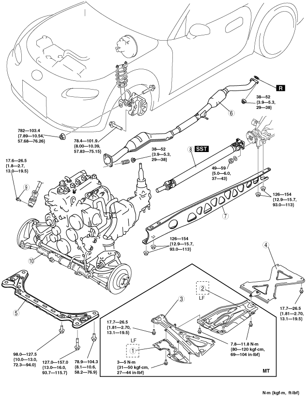
20. Remove the engine, transmission, and crossmember component using an engine lifter in the order indicated in the table.
amxzzw00001424
|
|
1
|
Under guard (LF MT)
|
|
2
|
Insulator (LF MT)
|
|
3
|
Member bracket (MT)
|
|
4
|
Tunnel member
|
|
5
|
Transverse member
|
|
6
|
Middle pipe
|
|
7
|
Power plant frame
|
|
8
|
Propeller shaft
|
|
9
|
Bolt (Intermediate Shaft)
|
|
10
|
Engine, transmission, crossmember component
|
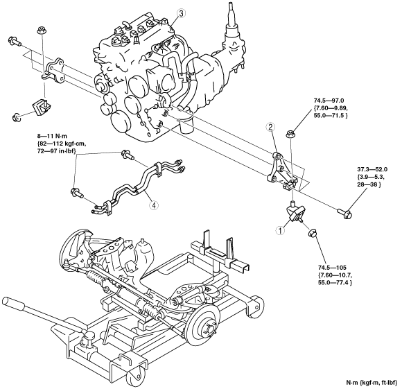
21. Remove the engine and transmission from the crossmember component lifter in the order indicated in the table by suspending them with a crane.
e5u110zw5103
|
|
1
|
Engine mount rubber
|
|
2
|
Engine mount bracket
|
|
3
|
Engine, transmission
|
|
4
|
Oil pipe, oil hose
|
22. Install in the reverse order of removal.
23. Start the engine and inspect and adjust the following:
24. Perform the on-road test and verify that there is no vibration or noise.
Engine, Transmission, Crossmember Component Removal Note
1. Secure the engine, transmission, and crossmember component using an engine lifter.