 |
amxuuw00004297
ENGINE DISASSEMBLY/ASSEMBLY [SKYACTIV-G 1.5, SKYACTIV-G 2.0]
id0110h8800500
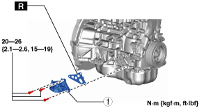
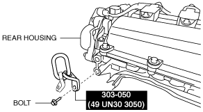
1. Install the SST and the following bolt to the position shown in the figure.
Engine rear side
amxuuw00004297
|
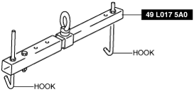
2. Engage the hooks of the SST (49 L017 5A0) to the SST (49 UN30 3050).
am6zzw00011714
|
3. To ensure the safety of the work (control engine and transmission sway), set a hoist.
4. Remove the engine mount rubber and engine mount bracket. (See ENGINE MOUNT DISASSEMBLY/ASSEMBLY [SKYACTIV-G 1.5, SKYACTIV-G 2.0].)
5. Remove the exhaust system. (See EXHAUST SYSTEM REMOVAL/INSTALLATION [SKYACTIV-G 1.5, SKYACTIV-G 2.0].)
6. Remove the oil pipes and oil hoses. (AT) (See OIL COOLER REMOVAL/INSTALLATION [SJ6A-EL].)
7. Remove the starter. (See STARTER REMOVAL/INSTALLATION [SKYACTIV-G 1.5, SKYACTIV-G 2.0].)
8. Fix the drive plate using the crankshaft pulley lock bolt. (AT)
9. Remove the torque converter installation nut from the starter installation hole. (AT) (See AUTOMATIC TRANSMISSION REMOVAL/INSTALLATION [SJ6A-EL].)
10. Disconnect the engine and transmission, and lower only the engine from the engine lifter. (See TRANSMISSION REMOVAL/INSTALLATION [M66M-D] (MT).) (See AUTOMATIC TRANSMISSION REMOVAL/INSTALLATION [SJ6A-EL] (AT).)
11. Remove the intake-air system. (See INTAKE-AIR SYSTEM REMOVAL/INSTALLATION [SKYACTIV-G 1.5, SKYACTIV-G 2.0].)
12. Remove the oil separator. (See POSITIVE CRANKCASE VENTILATION (PCV) VALVE REMOVAL/INSTALLATION [SKYACTIV-G 1.5, SKYACTIV-G 2.0].)
13. Remove the knock sensor (KS). (See KNOCK SENSOR (KS) REMOVAL/INSTALLATION [SKYACTIV-G 1.5, SKYACTIV-G 2.0].)
14. Remove the fuel injectors. (See FUEL INJECTOR REMOVAL/INSTALLATION [SKYACTIV-G 1.5, SKYACTIV-G 2.0].)
15. Remove the camshaft position (CMP) sensor. (See CAMSHAFT POSITION (CMP) SENSOR REMOVAL/INSTALLATION [SKYACTIV-G 1.5, SKYACTIV-G 2.0].)
16. Remove the high pressure fuel pump and rear housing. (See HIGH PRESSURE FUEL PUMP REMOVAL/INSTALLATION [SKYACTIV-G 1.5, SKYACTIV-G 2.0].)
17. Remove the electric variable valve timing motor/driver. (See ELECTRIC VARIABLE VALVE TIMING MOTOR/DRIVER REMOVAL/INSTALLATION [SKYACTIV-G 1.5, SKYACTIV-G 2.0].)
18. Remove the water outlet component. (See TIMING CHAIN REMOVAL/INSTALLATION [SKYACTIV-G 1.5, SKYACTIV-G 2.0].)
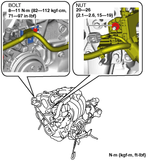
19. Remove the bolt and nut shown in the figure.
amxuuw00004298
|
20. Remove the drive belt auto tensioner. (See DRIVE BELT AUTO TENSIONER REMOVAL/INSTALLATION [SKYACTIV-G 1.5, SKYACTIV-G 2.0].)
21. Remove the generator. (See GENERATOR REMOVAL/INSTALLATION [WITHOUT i-ELOOP (SKYACTIV-G 1.5, SKYACTIV-G 2.0)].) (See GENERATOR REMOVAL/INSTALLATION [WITH i-ELOOP (SKYACTIV-G 1.5, SKYACTIV-G 2.0)].)
22. Remove the oil filter. (See OIL FILTER REPLACEMENT [SKYACTIV-G 1.5, SKYACTIV-G 2.0].)
23. Remove the engine oil solenoid valve. (See ENGINE OIL SOLENOID VALVE REMOVAL/INSTALLATION [SKYACTIV-G 1.5, SKYACTIV-G 2.0].)
24. Remove the crankshaft position (CKP) sensor. (See CRANKSHAFT POSITION (CKP) SENSOR REMOVAL/INSTALLATION [SKYACTIV-G 1.5, SKYACTIV-G 2.0].)
25. Remove the dipstick.
26. Remove the seal cover. (See SEAL COVER REMOVAL/INSTALLATION [SKYACTIV-G 1.5, SKYACTIV-G 2.0].)
27. Remove the ignition coil/ion sensors. (See IGNITION COIL/ION SENSOR REMOVAL/INSTALLATION [SKYACTIV-G 1.5, SKYACTIV-G 2.0].)
28. Remove the emission harness.
29. Remove the water pump drive belt. (See DRIVE BELT REMOVAL/INSTALLATION [SKYACTIV-G 1.5, SKYACTIV-G 2.0].)
30. Remove the water pump housing and water pump body. (See WATER PUMP REMOVAL/INSTALLATION [SKYACTIV-G 1.5, SKYACTIV-G 2.0].)
31. Remove the clutch cover and clutch disc. (MT) (See CLUTCH UNIT REMOVAL/INSTALLATION [SKYACTIV-G 1.5].) (See CLUTCH UNIT REMOVAL/INSTALLATION [SKYACTIV-G 2.0].)
32. Remove in the order indicated in the table.
33. Assemble in the reverse order of disassembly.
amxuuw00004299
|
|
1
|
Oil filter body
|
Oil Filter Body Installation Note
1. After tightening the three bolts, tighten the first tightened bolt to the specified tightening torque again.