 |
amxzzn00001277
INSTRUMENT CLUSTER
id092200018500
Outline
Functions
Speedometer display function
Tachometer display function
Fuel gauge display function
Odometer/tripmeter display function
Trip computer calculation function
Warning/indicator light turn on/flash function, message/system operation status display function
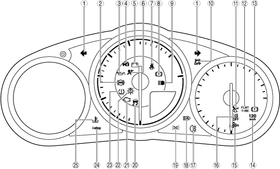
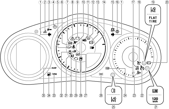
Without multi-information display
amxzzn00001277
|
|
No. |
Warning light/Indicator light |
Name |
Message is displayed in center display when warning/indicator light turns on/flashes |
Comment |
Warning/indicator light turned on when ignition is switched ON (engine off or on) |
Reference |
|---|---|---|---|---|---|---|
|
1
|
 |
Direction indicator/hazard warning indicator lights
|
—
|
—
|
—
|
|
|
2
|
 |
Low engine coolant temperature indicator light (blue)/high engine coolant temperature warning light (red)
|
×
|
—
|
×
|
|
|
3
|
 |
Wrench indicator light
|
—
|
—
|
×
|
|
|
4
|
 |
Low washer fluid level warning light
|
×
|
With headlight cleaner system
|
—
|
|
|
5
|
 |
Engine oil warning light
|
×
|
—
|
×
|
|
|
6
|
 |
Seat belt warning light
|
—
|
—
|
—
|
(See SEAT BELT WARNING LIGHT.)
|
|
7
|
 |
ABS warning light
|
×
|
—
|
×
|
|
|
8
|
 |
Master warning light
|
×
|
—
|
×
|
|
|
9
|
 |
Charging system warning light
|
×
|
—
|
×
|
|
|
10
|
 |
Air bag/seat belt pre-tensioner system warning light
|
×
|
—
|
×
|
|
|
11
|
 |
Security indicator light
|
—
|
—
|
×
|
(See SECURITY INDICATOR LIGHT.)
|
|
12
|
 |
Tire pressure monitoring system warning light
|
×
|
With tire pressure monitoring system
|
×
|
|
|
13
|
 |
Brake system warning light (red)
|
×
|
—
|
×
|
|
|
14
|
 |
Headlight high-beam indicator light
|
—
|
—
|
—
|
|
|
15
|
 |
DSC OFF indicator light
|
—
|
—
|
×
|
|
|
16
|
 |
LED headlight warning light
|
×
|
—
|
×
|
(See LED HEADLIGHT WARNING LIGHT.)
|
|
17
|
 |
LDWS OFF indicator light
|
—
|
With lane departure warning system (LDWS)
|
×
|
(See LDWS OFF INDICATOR LIGHT.)
|
|
18
|
 |
Active bonnet warning light
|
×
|
With active bonnet
|
×
|
(See ACTIVE BONNET WARNING LIGHT.)
|
|
19
|
 |
LDWS warning light
|
×
|
With lane departure warning system (LDWS) and without flat tire warning light
|
×
|
(See LDWS WARNING LIGHT.)
|
 |
Flat tire warning light
|
×
|
With flat tire warning light
|
×
|
||
|
20
|
|
Electric vacuum pump warning light (amber)
|
—
|
—
|
×
|
|
|
21
|
 |
Adjustable speed limiter main indicator light (amber)/adjustable speed limiter set indicator light (green)
|
—
|
With adjustable speed limiter
|
—
|
|
 |
120 km/h warning light
|
—
|
With 120 km/h warning light
|
×
|
(See 120 km/h WARNING LIGHT.)
|
|
|
22
|
 |
Cruise main indicator light (amber)/cruise set indicator light (green)
|
—
|
With cruise control system
|
—
|
|
|
23
|
 |
Blind spot monitoring (BSM) OFF indicator light
|
—
|
With blind spot monitoring (BSM) system
|
×
|
|
|
24
|
 |
HBC indicator light (green)/HBC warning light (amber)/Adaptive LED headlights indicator light (green)/adaptive LED headlights warning light (amber)
|
×
|
With high beam control (HBC) system or adaptive LED headlights
|
×
|
|
|
25
|
 |
Rear fog light indicator light
|
—
|
With rear fog light
|
—
|
|
|
LDWS warning light
|
—
|
With lane departure warning system (LDWS) and flat tire warning light
|
×
|
(See LDWS WARNING LIGHT.)
|
|
|
26
|
 |
Lights-on indicator light
|
—
|
—
|
—
|
(See LIGHTS-ON INDICATOR LIGHT.)
|
|
27
|
 |
Power steering malfunction indicator light
|
×
|
—
|
×
|
|
|
28
|
 |
TCS/DSC indicator light
|
×
|
—
|
×
|
(See TCS/DSC INDICATOR LIGHT.)
|
|
29
|
 |
Check engine light
|
×
|
—
|
×
|
|
|
30
|
 |
Automatic transmission warning light
|
×
|
AT
|
×
|
|
|
31
|
 |
KEY warning light (red)/KEY indicator light (green)
|
×
|
—
|
×
|
|
|
32
|
 |
Door-ajar warning light
|
—
|
—
|
—
|
(See DOOR-AJAR WARNING LIGHT.)
|
|
33
|
 |
i-stop warning light (amber)/i-stop indicator light (green)
|
×
|
With i-stop system
|
×
|
|
|
34
|
 |
Low fuel warning light
|
×
|
—
|
—
|
|
|
35
|
 |
i-ELOOP indicator light (green)/i-ELOOP warning light (amber)
|
×
|
With i-ELOOP
|
×
|
With multi-information display
amxzzn00001314
|
|
No. |
Warning light/Indicator light |
Name |
Message is displayed in center display when warning/indicator light turns on/flashes |
Comment |
Warning/indicator light turned on when ignition is switched ON (engine off or on) |
Reference |
|---|---|---|---|---|---|---|
|
1
|
|
Direction indicator/hazard warning indicator lights
|
—
|
—
|
—
|
|
|
2
|
|
ABS warning light
|
×
|
—
|
×
|
|
|
3
|
|
Engine oil warning light
|
×
|
—
|
×
|
|
|
4
|
|
Security indicator light
|
—
|
—
|
×
|
(See SECURITY INDICATOR LIGHT.)
|
|
5
|
|
Charging system warning light
|
×
|
—
|
×
|
|
|
6
|
|
Air bag/seat belt pre-tensioner system warning light
|
×
|
—
|
×
|
|
|
7
|
|
Seat belt warning light
|
—
|
—
|
—
|
(See SEAT BELT WARNING LIGHT.)
|
|
8
|
|
Brake system warning light (red)
|
×
|
—
|
×
|
|
|
9
|
|
Headlight high-beam indicator light
|
—
|
—
|
—
|
|
|
10
|
|
DSC OFF indicator light
|
—
|
—
|
×
|
|
|
11
|
|
Active bonnet warning light
|
×
|
With active bonnet
|
×
|
(See ACTIVE BONNET WARNING LIGHT.)
|
|
12
|
|
Flat tire warning light
|
×
|
With flat tire warning light
|
×
|
|
|
13
|
|
Electric vacuum pump warning light (amber)
|
—
|
—
|
×
|
|
|
14
|
|
120 km/h warning light
|
—
|
With 120 km/h warning light
|
×
|
(See 120 km/h WARNING LIGHT.)
|
|
15
|
|
Blind spot monitoring (BSM) OFF indicator light
|
—
|
With blind spot monitoring (BSM) system
|
×
|
|
|
16
|
|
LDWS OFF indicator light
|
—
|
With lane departure warning system (LDWS)
|
×
|
(See LDWS OFF INDICATOR LIGHT.)
|
|
17
|
|
Rear fog light indicator light
|
—
|
With rear fog light
|
—
|
|
|
18
|
|
HBC indicator light (green)/HBC warning light (amber)/Adaptive LED headlights indicator light (green)/adaptive LED headlights warning light (amber)
|
×
|
With high beam control (HBC) system or adaptive LED headlights
|
×
|
|
|
19
|
|
Lights-on indicator light
|
—
|
—
|
—
|
(See LIGHTS-ON INDICATOR LIGHT.)
|
|
20
|
|
TCS/DSC indicator light
|
×
|
—
|
×
|
(See TCS/DSC INDICATOR LIGHT.)
|
|
21
|
|
Check engine light
|
×
|
—
|
×
|
|
|
22
|
|
LED headlight warning light
|
×
|
—
|
×
|
(See LED HEADLIGHT WARNING LIGHT.)
|
|
23
|
|
Tire pressure monitoring system warning light
|
×
|
With tire pressure monitoring system
|
×
|
|
|
24
|
|
i-stop warning light (amber)/i-stop indicator light (green)
|
×
|
With i-stop system
|
×
|
|
|
25
|
|
Low engine coolant temperature indicator light (blue)/high engine coolant temperature warning light (red)
|
×
|
—
|
×
|
Buzzer operation function
|
Name |
Reference |
|---|---|
|
Lights-on reminder warning alarm
|
|
|
Seat belt warning alarm
|
(See SEAT BELT WARNING ALARM.)
|
|
Keyless warning alarm
|
(See KEYLESS WARNING ALARM.)
|
|
Air bag system warning alarm
|
(See AIR BAG SYSTEM WARNING ALARM.)
|
|
Blind spot monitoring (BSM) warning buzzer (with blind spot monitoring (BSM) system)
|
|
|
Lane departure warning sound (with lane departure warning system (LDWS))
|
(See LANE DEPARTURE WARNING SOUND.)
|
|
i-stop indicator alarm (with i-stop system)
|
|
|
i-stop warning alarm (with i-stop system)
|
|
|
Active bonnet warning alarm (with active bonnet)
|
(See ACTIVE BONNET WARNING ALARM.)
|
|
Turn and hazard indicator alarm
|
|
|
120 km/h warning alarm (with 120 km/h warning alarm)
|
(See 120 km/h WARNING ALARM.)
|
|
Adjustable speed limiter warning alarm (with adjustable speed limiter)
|
|
|
Vehicle speed alarm (with vehicle speed alarm)
|
|
|
Tire pressure monitoring system warning alarm (with tire pressure monitoring system)
|
|
|
Panel light control indicator alarm
|
|
|
Ambient temperature warning alarm (with ambient temperature warning alarm)
|
|
|
Retractable hardtop warning beep (with retractable hardtop)
|
With ignition switched off
|
Order of precedence |
Name |
|---|---|
|
1
|
Keyless warning alarm (pattern A, B)
|
|
2
|
Lights-on reminder warning alarm
|
|
3
|
Keyless warning alarm (pattern C)
|
|
4
|
Turn and hazard indicator alarm
|
|
5
|
Panel light control indicator alarm
|
With ignition switched ON (engine off or on)
|
Order of precedence |
Name |
|---|---|
|
1
|
Blind spot monitoring (BSM) warning buzzer (rear cross traffic alert (RCTA) function)
|
|
2
|
120 km/h warning alarm
|
|
3
|
i-stop warning alarm
|
|
4
|
Seat belt warning alarm
|
|
5
|
Retractable hardtop warning beep
|
|
6
|
Tire pressure monitoring system warning alarm
|
|
7
|
Adjustable speed limiter warning alarm
|
|
8
|
Blind spot monitoring (BSM) warning buzzer (blind spot monitoring (BSM) function)
|
|
9
|
Lane departure warning sound
|
|
10
|
Keyless warning alarm
|
|
11
|
Air bag system warning alarm
|
|
12
|
Active bonnet warning alarm
|
|
13
|
Ambient temperature warning alarm
|
|
14
|
Vehicle speed alarm
|
|
15
|
Turn and hazard indicator alarm
|
|
16
|
Panel light control alarm
|
Panel Light Control Function
Vehicle Specification Information Transmission Function
Battery Discharge Suppression Function
Structural View
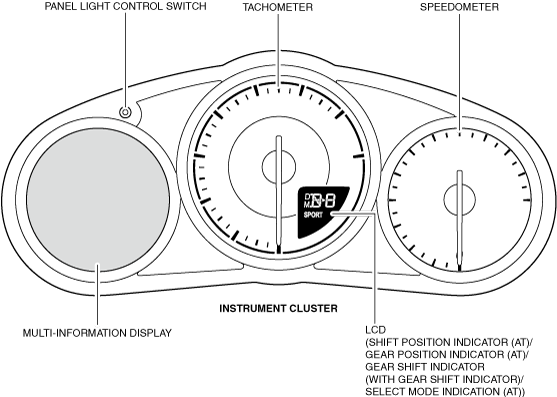
Without multi-information display
amxzzn00001315
|
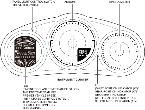
With multi-information display
amxzzn00001316
|
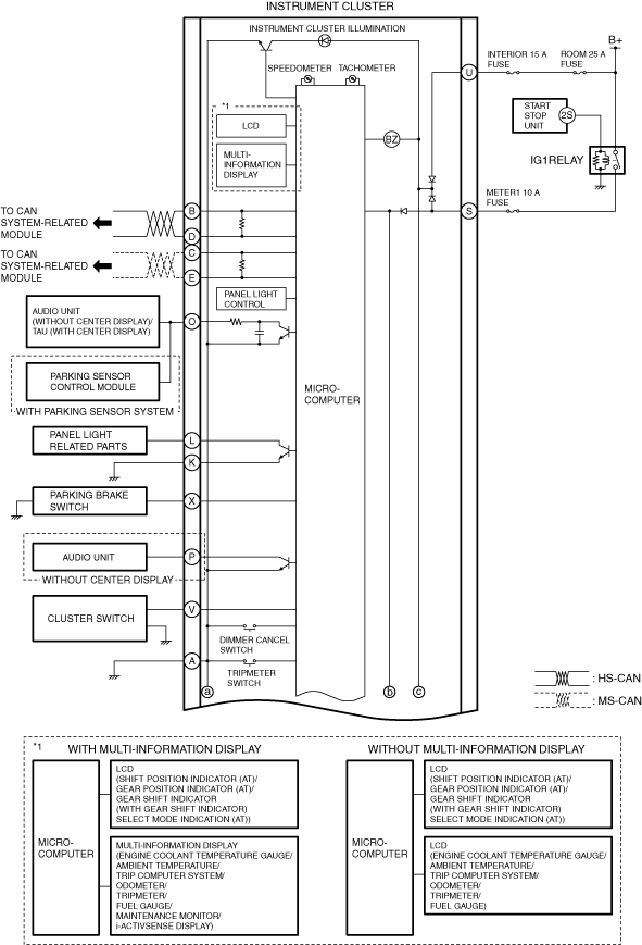
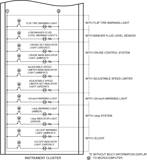
System Wiring Diagram
amxzzn00001317
|
amxzzn00001318
|
amxzzn00001319
|
amxzzn00001320
|
Fail-safe
Speedometer
Tachometer
Fuel gauge
Odometer/tripmeter
Engine coolant temperature gauge
Indicator light
Warning lights
Alarm
Panel light
Trip computer
Ambient temperature display