am2zzn00004855
|
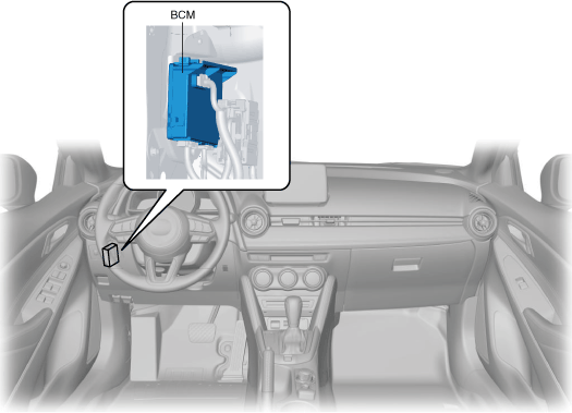
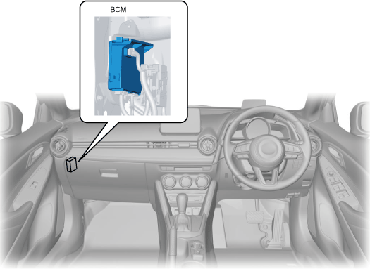
BODY CONTROL MODULE (BCM)
id094000004100
Purpose
Function
Control table
|
Control |
Content |
Reference |
|---|---|---|
|
Front fog light
|
The BCM performs control of the front fog light relay based on the signal from the front fog light switch.
|
(See FRONT FOG LIGHT.)
|
|
Turn light system
|
The BCM performs control of the turn light system based on the signal from the turn switch.
|
(See TURN LIGHT SYSTEM.)
|
|
Front map light
|
The BCM performs control of the front map light based on the signals from the door latch switch and interior light switch.
|
(See FRONT MAP LIGHT.)
|
|
Rear map light
|
The BCM performs control of the rear map light based on the signals from the door latch switch and interior light switch.
|
(See REAR MAP LIGHT.)
|
|
Cargo compartment light
|
The BCM performs control of the cargo compartment light based on the signals from the liftgate switch and cargo compartment light switch.
|
(See CARGO COMPARTMENT LIGHT.)
|
|
Coming home light system
|
The BCM performs control of the coming home light system based on the signals from the light switch and the door light switch.
|
(See COMING HOME LIGHT SYSTEM.)
|
|
Leaving home light system
|
The BCM performs control of the leaving home light system based on the signals from the light switch and the remote transmitter.
|
(See LEAVING HOME LIGHT SYSTEM.)
|
|
Power door lock system
|
The BCM performs control of the power door lock system based on the signal from the door look link switch or front door key cylinder switch.
|
(See POWER DOOR LOCK SYSTEM.)
|
|
Liftgate opener system
|
The BCM performs control of the liftgate opener system based on the signal from the liftgate opener switch.
|
(See LIFTGATE OPENER SYSTEM.)
|
|
Windshield wiper
|
The BCM performs control of the windshield wipers based on the signal from the wiper and washer switch.
|
|
|
Rear wiper and washer system
|
The BCM performs control of the rear wiper and washer system based on the signal from the wiper and washer switch.
|
(See REAR WIPER/WASHER SYSTEM.)
|
|
Blower system
|
The BCM performs control of the blower relay based on the request signal from the PCM.
|
(See BLOWER SYSTEM.)
|
|
Rear window defogger
|
The BCM performs control of the rear window defogger relay based on the signal from the climate control unit.
|
|
|
Horn
|
The BCM performs control of the horn relay based on the signal from the horn system.
|
(See HORN.)
|
|
Headlight cleaner
|
The BCM controls the headlight cleaner based on the signal from the wiper and washer switch.
|
(See HEADLIGHT CLEANER SYSTEM.)
|
|
Theft-deterrent system
|
The BCM controls the theft-deterrent system based on the signals from the door latch switch, liftgate latch switch, hood latch switch, and door lock link switch.
|
(See THEFT-DETERRENT SYSTEM.)
|
Battery Discharge Suppression Function
Dark current reduction function
Automatic configuration function
Construction
am2zzn00004855
|
am2zzn00004446
|
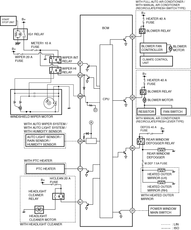
System Wiring Diagram
Windshield wiper, rear window defogger, blower motor, power window, headlight cleaner
am2zzn00004856
|
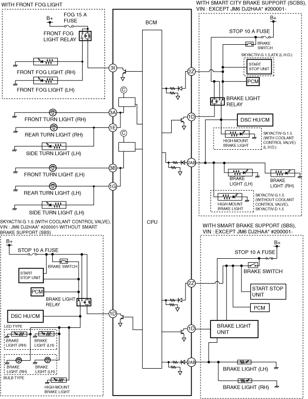
Front fog light, turn light, brake light
am2zzn00004950
|
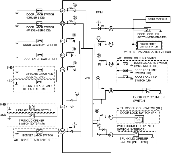
Door lock, liftgate opener
am2zzn00004951
|
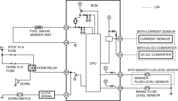
Fuel gauge sender unit, horn, brake fluid level sensor, current sensor, washer fluid-level sensor
am2zzn00004952
|
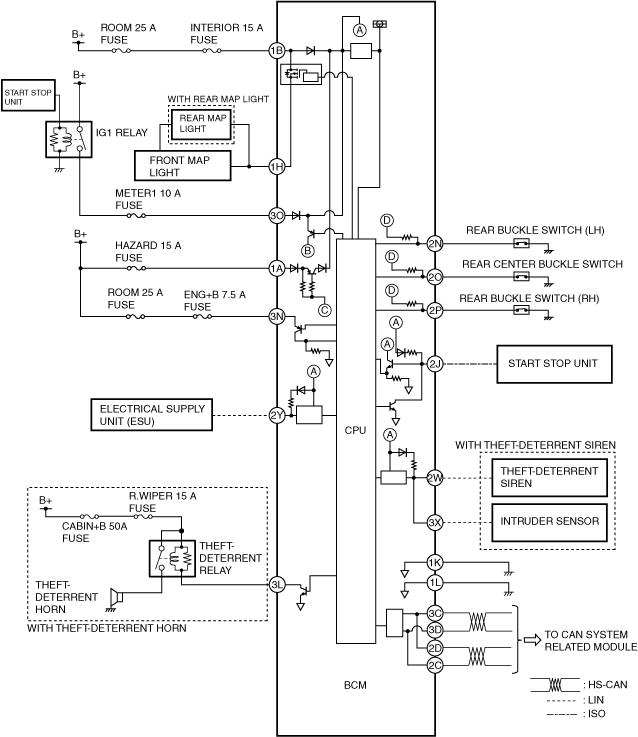
Power supply, LIN communication, ISO communication, CAN system, rear buckle switch, theft-deterrent system
am2zzn00004860
|
Operation
For the operation of each control, refer to the following system operations.
Fail-safe
Exterior lighting system
Auto-light system
Running light system
Interior light control system
Power door lock system
Liftgate opener system
Windshield wiper system
Front washer system
Auto wiper system
Blower system
Rear window defogger
Horn