 |
am3zzw00009933
ENGINE REMOVAL/INSTALLATION [MZR 2.0 DISI i-stop]
id011037800400
1. Remove the battery cover. (See BATTERY REMOVAL/INSTALLATION [MZR 2.0 DISI i-stop].)
2. Disconnect the negative battery cable.
3. Remove the plug hole plate. (See PLUG HOLE PLATE REMOVAL/INSTALLATION [MZR 2.0 DISI i-stop].)
4. Remove the battery tray. (See BATTERY REMOVAL/INSTALLATION [MZR 2.0 DISI i-stop].)
5. Remove the air cleaner component. (See INTAKE-AIR SYSTEM REMOVAL/INSTALLATION [MZR 2.0 DISI i-stop].)
6. Remove the front wheels and tires. (See GENERAL PROCEDURES (SUSPENSION).)
7. Remove the aerodynamic under cover No.2 and splash shield as a single unit. (See AERODYNAMIC UNDER COVER NO.2 REMOVAL/INSTALLATION.) (See SPLASH SHIELD REMOVAL/INSTALLATION.)
8. Drain the transaxle oil (MTX) or ATF (ATX). (See TRANSAXLE OIL REPLACEMENT [G66M-R](MTX).) (See AUTOMATIC TRANSAXLE FLUID (ATF) REPLACEMENT [FS5A-EL](ATX).)
9. Drain the engine coolant. (See ENGINE COOLANT REPLACEMENT [MZR 2.0 DISI i-stop].)
10. Remove the coolant reserve tank. (See COOLANT RESERVE TANK REMOVAL/INSTALLATION [MZR 2.0 DISI i-stop].)
11. Disconnect the fuel hose. (See QUICK RELEASE CONNECTOR REMOVAL/INSTALLATION [MZR 2.0 DISI i-stop].)
12. Disconnect the evaporative hose. (See QUICK RELEASE CONNECTOR REMOVAL/INSTALLATION [MZR 2.0 DISI i-stop].)
13. Disconnect the brake vacuum hose. (See VACUUM HOSE REMOVAL/INSTALLATION [LF, MZR 2.0 DISI i-stop, L5].)
14. Disconnect the radiator hose (upper and lower). (See RADIATOR REMOVAL/INSTALLATION [MZR 2.0 DISI i-stop].)
15. Disconnect the water hose. (See THERMOSTAT REMOVAL/INSTALLATION [MZR 2.0 DISI i-stop].)
16. Disconnect the heater hose. (See REFRIGERANT LINE REMOVAL/INSTALLATION.)
17. Disconnect the power steering pipe component and then drain the power steering fluid. (See GENERAL PROCEDURES (STEERING).)
18. Disconnect the selector cable. (ATX) (See TRANSAXLE RANGE (TR) SWITCH REMOVAL/INSTALLATION [FS5A-EL].)
19. Disconnect the oil hose and wiring harness. (ATX) (See AUTOMATIC TRANSAXLE REMOVAL/INSTALLATION [FS5A-EL].)
20. Disconnect the shift cable and selector cable. (MTX) (See MANUAL TRANSAXLE REMOVAL/INSTALLATION [G66M-R (MZR 2.0 DISI i-stop)].)
21. Remove the clutch release cylinder with the pipe still connected. (MTX) (See CLUTCH RELEASE CYLINDER REMOVAL/INSTALLATION [G66M-R].)
22. Remove the crossmember bracket. (See FRONT CROSSMEMBER REMOVAL/INSTALLATION [MZR 2.0 DISI i-stop].)
23. Remove the tunnel member (rear). (See EXHAUST SYSTEM REMOVAL/INSTALLATION [MZR 2.0 DISI i-stop].)
24. Set the TWC out of the way. (See EXHAUST SYSTEM REMOVAL/INSTALLATION [MZR 2.0 DISI i-stop].)
25. Disconnect the drive shafts from the engine side, set the drive shafts out of the way. (See DRIVE SHAFT REMOVAL/INSTALLATION.)
26. Remove the A/C drive belt. (See DRIVE BELT REMOVAL/INSTALLATION [MZR 2.0 DISI i-stop].)
27. Remove the A/C compressor with the cooler hose still connected and secure it using wire or rope so that it is out of the way. (See A/C COMPRESSOR REMOVAL/INSTALLATION.)
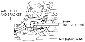
28. Remove the water pipe and bracket from the electric AT oil pump bracket and set it out of the way. (ATX)
am3zzw00009933
|
29. Remove the electric AT oil pump. (ATX) (See ELECTRIC AT OIL PUMP REMOVAL/INSTALLATION [FS5A-EL].)
30. Remove the electric AT oil pump bracket. (ATX) (See ELECTRIC AT OIL PUMP REMOVAL/INSTALLATION [FS5A-EL].)
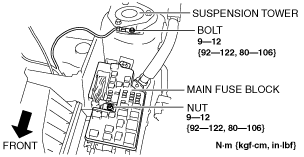
31. Remove the wiring harness installation bolt and nut shown in the figure.
am3zzw00009934
|
32. Disconnect the ground cable from the cylinder head cover bracket (RH).
33. Disconnect the connectors and the wiring harnesses related to the engine removal/installation.
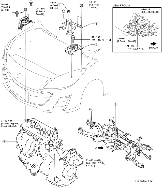
34. Remove in the order indicated in the table.
35. Install in the reverse order of removal.
36. Start the engine. And inspect and adjust the following:
am3zzw00007639
|
|
1
|
Battery tray bracket
|
|
2
|
No.1 engine mount rubber, front crossmember component
|
|
3
|
No.4 Engine mount rubber
|
|
4
|
No.3 Engine mount
|
|
5
|
Engine, transaxle
|
No.1 engine mount rubber, Front Crossmember Component Removal Note
1. Remove the No.1 engine mount rubber and the front crossmember as a single unit. (See FRONT CROSSMEMBER REMOVAL/INSTALLATION [MZR 2.0 DISI i-stop].)
No.3 Engine Mount and No.4 Engine Mount Rubber Removal Note
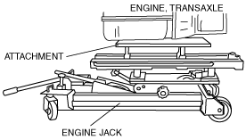
1. Secure the engine and the transaxle using an engine jack and attachment as shown in the figure.
am3zzw00002474
|
Engine Mount Installation Note
1. Tighten the No.3 engine mount bracket stud bolts.
am3zzw00002477
|
2. Secure the engine and the transaxle using an engine jack and attachment as shown in the figure.
am3zzw00002474
|
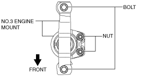
3. Temporarily tighten the No.3 engine mount installation bolts and nuts.
am3zzw00009935
|
4. Temporarily tighten the No.4 engine mount rubber installation bolt.
am3zzw00009936
|
5. Install the No.1 engine mount rubber and the front crossmember as a single unit. (See FRONT CROSSMEMBER REMOVAL/INSTALLATION [MZR 2.0 DISI i-stop].)
6. Temporarily tighten the No.1 engine mount rubber installation bolts in the order as shown in the figure.
am3zzw00009058
|
7. Tighten the No.3 engine mount installation bolts and nuts in the order shown in the figure.
am3zzw00009937
|
|
No. |
Tightening torque |
|---|---|
|
1
|
75—104 N·m {7.7—10 kgf·m, 56—76 ft·lbf}
|
|
2
|
71—93 N·m {7.3—9.4 kgf·m, 53—68 ft·lbf}
|
8. Tighten the No.4 engine mount rubber installation bolt as shown in the figure.
am3zzw00009936
|
9. Tighten the No.1 engine mount rubber installation bolts as shown in the figure.
am3zzw00009058
|
|
No. |
Tightening torque |
|---|---|
|
1
|
71—91 N·m {7.3—9.2 kgf·m, 53—67 ft·lbf}
|
|
2, 3
|
94—116 N·m {9.6—11 kgf·m, 70—85 ft·lbf}
|
|
4
|
73—90 N·m {7.5—9.1 kgf·m, 54—66 ft·lbf}
|