ENGINE REMOVAL/INSTALLATION [MZ-CD 1.6 (Y6)]
id0110b2800400
-
Warning
-
• Fuel vapor is hazardous. It can very easily ignite, causing serious injury and damage. Always keep sparks and flames away from fuel.
• Fuel line spills and leakage are dangerous. Fuel can ignite and cause serious injuries or death and damage. Fuel can also irritate skin and eyes. To prevent this, always complete the “Fuel Line Safety Procedure”. (See
BEFORE SERVICE PRECAUTION [MZ-CD 1.6 (Y6)].)
-
Note
-
• Perform the engine and transaxle component removal/installation from below the vehicle.
1. Remove the following parts:
- (1) Engine cover
- (2) Battery cover, battery box, battery clamp, battery and battery tray (See BATTERY REMOVAL/INSTALLATION [MZ-CD 1.6 (Y6)].)
- (3) Front wheels and tires (See GENERAL PROCEDURES (SUSPENSION).)
- (4) Under cover and splash shields
2. Drain the following fluids:
- (1) Transaxle oil (See TRANSAXLE OIL REPLACEMENT [J65M-R].)
- (2) Engine coolant (See ENGINE COOLANT REPLACEMENT [MZ-CD 1.6 (Y6)].)
3. Disconnect the following parts:
- (1) Brake hose (See FRONT BRAKE (DISC) REMOVAL/INSTALLATION [EXCEPT L3 Turbo].)
- (2) Stabilizer control link and ABS sensor bracket (See FRONT STABILIZER REMOVAL/INSTALLATION [EXCEPT MZR-CD (RF Turbo)].)
- (3) Tie-rod end (See STEERING GEAR AND LINKAGE REMOVAL/INSTALLATION.)
- (4) Front lower arm boll joint (See FRONT LOWER ARM REMOVAL/INSTALLATION.)
- (5) Drive shaft (See DRIVE SHAFT REMOVAL/INSTALLATION.)
4. Remove the coolant reserve tank. (See COOLANT RESERVE TANK REMOVAL/INSTALLATION [MZ-CD 1.6 (Y6)].)
5. Remove fuel filter protector (See FUEL FILTER (HIGH-PRESSURE) REMOVAL/INSTALLATION [MZ-CD 1.6 (Y6)].)
6. Remove the following parts (A/C equipped vehicles):
- (1) Air cleaner and air hose component, charge air cooler pipe and hose, air hose (See INTAKE-AIR SYSTEM REMOVAL/INSTALLATION [MZ-CD 1.6 (Y6)].)
- (2) Catalytic converter insulator and catalytic converter insulator bracket (See EXHAUST SYSTEM REMOVAL/INSTALLATION [MZ-CD 1.6 (Y6)].)
- (3) Oil level gauge pipe
- (4) Drive belt
- (5) Drive belt auto tensioner
- (6) Generator (See GENERATOR REMOVAL/INSTALLATION [MZ-CD 1.6 (Y6)].)
- (7) A/C compressor with the pipes still connected
-
-
Note
-
• Secure the A/C compressor using wire or rope so that it is out of the way.
7. Remove the air cleaner and air hose component, charge air cooler hose (A/C non-equipped vehicles) (See INTAKE-AIR SYSTEM REMOVAL/INSTALLATION [MZ-CD 1.6 (Y6)].):
8. Disconnect the following parts:
- (1) Upper and lower radiator hose (engine side)
- (2) Fuel main hose (engine side)
- (3) Fuel return hose (engine side)
- (4) Heater hose (engine side)
- (5) Heater hose (thermostat case side)
- (6) Brake vacuum hose (vacuum pump side)
- (7) Vacuum hose (brake vacuum hose side)
- (8) Shift cable (See MANUAL TRANSAXLE REMOVAL/INSTALLATION [J65M-R].)
9. Remove the following parts:
- (1) Shift cable bracket (See MANUAL TRANSAXLE REMOVAL/INSTALLATION [J65M-R].)
- (2) Clutch pipe connector (See MANUAL TRANSAXLE REMOVAL/INSTALLATION [J65M-R].)
- (3) PCM cover
10. Disconnect the PCM connector.
11. Remove the harness bracket (reinforcement).
12. Disconnect the fan control module connector.
13. Remove the following parts:
- (1) Cooling fan component (See RADIATOR REMOVAL/INSTALLATION [MZ-CD 1.6 (Y6)].)
14. Disconnect the front pipe (See EXHAUST SYSTEM REMOVAL/INSTALLATION [MZ-CD 1.6 (Y6)].)
15. Remove in the order indicated in the table.
16. Install in the reverse order of removal.
17. Perform the air bleeding of clutch fluid. (See CLUTCH FLUID AIR BLEEDING/REPLACEMENT.)
18. Inspect the following and adjust them if necessary.
-
• Pulley and belt for runout and contact.
• Leakage of engine oil, engine coolant, MTX oil, and fuel.
• Engine-driven accessories operation
-
Note
-
• If the engine is overhauled and installed to the vehicle, perform the road test and verify that there is no abnormality.
|
1
|
|
|
2
|
No.1 Engine mount rubber
|
|
3
|
|
|
4
|
Battery tray bracket
|
|
5
|
No.4 Engine mount rubber
|
|
6
|
Engine, transaxle
|
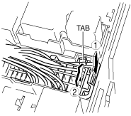
Main Fuse Block Connector Removal Note
1. Release the tab in the order shown in the figure.
2. Pull the lock lever up and remove the connector.
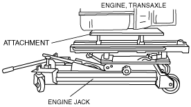
No.3 Engine Mount Rubber Removal Note
1. Secure the engine and the transaxle using an engine jack and attachment.
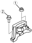
No.4 Engine Mount Rubber Installation Note
1. Secure the engine and the transaxle using an engine jack and attachment.
2. No.4 engine mount rubber.
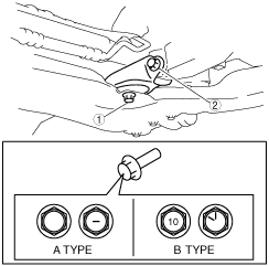
3. Tighten the No.4 engine mount rubber installation bolt shown in the figure.
-
Caution
-
• If the No.4 engine mount rubber installation bolt is A type, replace it with B type bolt and tighten.
-
Tightening torque
A type: 83.6—113.1 N·m {8.6—11.5 kgf·m, 61.7—83.4 ft·lbf}
B type: 129.9—152.7 N·m {13.3—15.5 kgf·m, 95.9—112.6 ft·lbf}
4. Tighten the No.4 engine mount rubber and battery tray bracket installation bolt and nut in the order shown in the figure.
-
Tightening torque
-
1: 44—61 N·m {4.5—6.2 kgf·m, 33—44 ft·lbf}
2: 6.9—9.8 N·m {70.4—99.9 kgf·cm, 61.1—86.7 in·lbf}
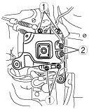
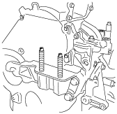
No.3 Engine Mount Rubber Installation Note
1. Tighten the No.3 engine mount installation stud bolts.
-
Tightening torque
-
7—13 N·m {0.8—1.3 kgf·m, 5.2—9.5 ft·lbf}
2. Install the No.3 engine mount, and then temporarily tighten the installation bolts and nuts.
3. Tighten the installation bolts in the order shown in the figure.
-
Tightening torque
-
1 (nuts): 74.5—104.9 N·m {7.60—10.69 kgf·m, 55.0—77.3 ft·lbf}
2 (bolts): 74.5—93.1 N·m {7.60—9.49 kgf·m, 55.0—68.6 ft·lbf}
No.1 Engine Mount Rubber Installation Note
1. Remove the engine jack and attachment.
2. Install the No.1 engine mount rubber to the cross member and temporarily tighten bolts.
3. Tighten the No.1 engine mount rubber installation bolts.
-
Caution
-
• Tighten the bolts in the order shown in the figure to prevent abnormal noise and vibration after assembly.
• Tighten the bolts while being careful of their length to prevent interference between the steering gear housing and bolt.
-
Bolt length (measured from below the head)
-
Front crossmember side: 62 mm {2.441 in}
No.1 engine mount bracket side: 65 mm {2.559 in}
-
Tightening torque
-
A type: 72.6—90.9 N·m {7.5—9.2 kgf·m, 53.6—67.0 ft·lbf}
B type: 104.2—132.6 N·m {10.7—13.5 kgf·m, 76.9—97.8 ft·lbf}