 |
am3zzw00004500
BRAKE PEDAL REMOVAL/INSTALLATION [EXCEPT MZ-CD 1.6 (Y6)]
id041100801285
1. Remove the charge air cooler cover. (L3 Turbo) (See INTAKE AIR SYSTEM REMOVAL/INSTALLATION [L3 Turbo].)
2. Remove the exhaust insulator. (R.H.D. L3 Turbo) (See EXHAUST SYSTEM REMOVAL/INSTALLATION [L3 Turbo].)
3. Remove the charge air cooler. (R.H.D. L3 Turbo) (See INTAKE AIR SYSTEM REMOVAL/INSTALLATION [L3 Turbo].)
4. Remove the battery and battery tray. (L.H.D.) (See BATTERY REMOVAL/INSTALLATION [ZJ, ZY, Z6].) (See BATTERY REMOVAL/INSTALLATION [LF, L3].) (See BATTERY REMOVAL/INSTALLATION [L3 Turbo].) (See BATTERY REMOVAL/INSTALLATION [MZR-CD (RF Turbo)].)
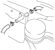
5. Disconnect the vacuum hose from the insulator pipe as shown in the figure. (L.H.D. L3 Turbo)
am3zzw00004500
|
6. Remove the insulator. (L.H.D. L3 Turbo) (see MASTER CYLINDER REMOVAL/INSTALLATION [L.H.D. L3 Turbo].)
7. Disconnect the brake pipe (master cylinder side). (L.H.D.) (See MASTER CYLINDER REMOVAL/INSTALLATION [L.H.D. EXCEPT L3 Turbo].) (See MASTER CYLINDER REMOVAL/INSTALLATION [L.H.D. L3 Turbo].)
8. Remove the accelerator pedal. (See ACCELERATOR PEDAL REMOVAL/INSTALLATION [ZJ, ZY, Z6].) (See ACCELERATOR PEDAL REMOVAL/INSTALLATION [LF, L3].) (See ACCELERATOR PEDAL REMOVAL/INSTALLATION [L3 Turbo].) (See ACCELERATOR PEDAL REMOVAL/INSTALLATION [MZR-CD (RF Turbo)].)
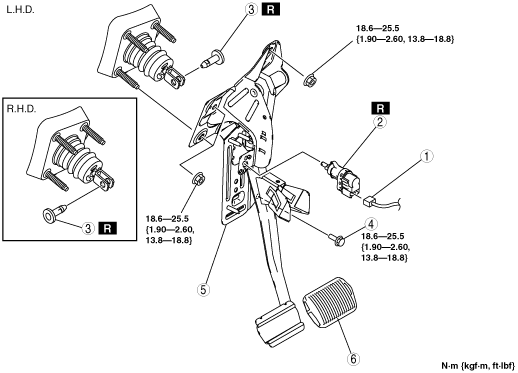
9. Remove in the order indicated in the table.
10. Install in the reverse order of removal.
11. Adjust the accelerator cable. (without throttle valve actuator) (See ACCELERATOR CABLE INSPECTION/ADJUSTMENT [ZJ, ZY, Z6].)
am3zzw00004501
|
|
1
|
Brake switch connector
|
|
2
|
Brake switch
|
|
3
|
Joint pin
(See Joint Pin Installation Note.)
|
|
4
|
Bolt (L.H.D.)
|
|
5
|
Brake pedal
(See Brake Pedal Removal Note.)
|
|
6
|
Pedal pad
|
Brake Pedal Removal Note
1. Remove the brake pedal installation nuts.
2. Move the power brake unit to the vehicle front where the power brake unit fork does not interfere with the brake pedal arm.
3. Remove the brake pedal.
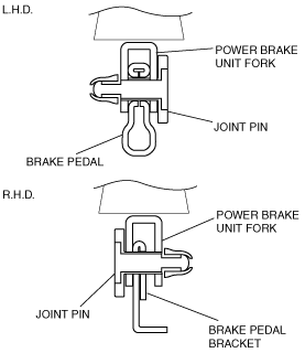
Joint Pin Installation Note
1. For L.H.D., install the new joint pin by aligning the pin holes of the brake pedal and power brake unit fork.
2. For R.H.D., install the new joint pin by aligning the pin holes of the brake pedal bracket and power brake unit fork.
3. Verify that the joint pin touches the power brake unit fork completely.
am3zzw00004502
|
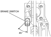
Brake Switch Installation Note
1. Inspect the brake pedal. (See BRAKE PEDAL INSPECTION.)
2. With the brake pedal fully released, insert a new brake switch into the installation hole on the brake pedal.
3. Secure the brake switch by turning it counterclockwise 45°.
am3zzw00004503
|