NO.3 WILL NOT CRANK [MZR 2.0 DISI i-stop]


id0103d3800900

Vehicles Without Advanced Keyless Entry And Push Button Start System

3

WILL NOT CRANK

DESCRIPTION
•  Starter does not work.
POSSIBLE CAUSE
•  Poor connection of coil antenna connector
•  Instrument cluster or related wiring harness malfunction
•  Immobilizer system malfunction
•  Following circuit and connector malfunction:
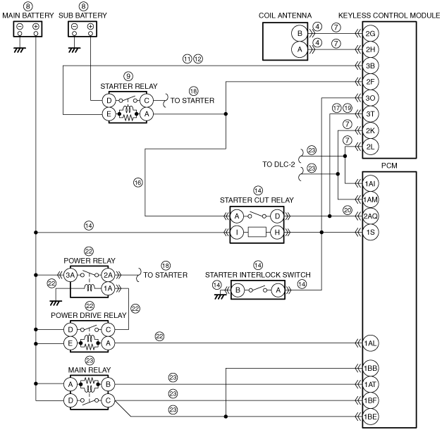
―  Between coil antenna terminal B and instrument cluster terminal 2M
―  Between coil antenna terminal A and instrument cluster terminal 2Q
―  Between PCM terminal 1AI and instrument cluster terminal 2D
―  Between PCM terminal 1AM and instrument cluster terminal 2B
•  Main battery malfunction
•  Sub battery malfunction
•  Fuse malfunction
•  Open circuit in wiring harness between PCM terminal 2AQ and starter relay terminal A
•  Starter interlock switch or related wiring harness malfunction
•  Starter relay or related wiring harness malfunction
•  Ignition switch or related wiring harness malfunction
•  Following circuit malfunction:
―  Between starter relay terminal D and sub battery positive terminal
―  Between starter relay terminal C and starter
―  Between main battery positive terminal and power relay
―  Between power relay and starter
•  Open circuit in wiring harness between power drive relay terminal A and PCM terminal 1AL
•  Open circuit in wiring harness between power drive relay terminal C and power relay
•  Power drive relay malfunction
•  Power relay malfunction
•  Power relay ground malfunction
•  Starting system malfunction
•  Seized/hydro locked engine, flywheel
•  PCM continuous memory DTC is stored.
•  Open circuit in wiring harness between the following terminals:
―  Main relay terminal B—PCM terminal 1AT
―  Main relay terminal C—PCM terminal 1BE or 1BF
―  DLC-2—PCM terminal 1AM or 1AI
•  Main relay malfunction (stuck open)
•  Open or poor ground circuit
•  Poor connection of vehicle body ground
•  PCM DTC is stored.
•  Start circuit in ignition switch malfunction
•  Open circuit in wiring harness between ignition switch and starter

Diagnostic procedure

STEP

INSPECTION

RESULTS

ACTION

1
Turn off the i-stop system.
Verify the symptom.
Is the symptom confirmed?
Yes
Go to the next step.
No
Perform the symptom troubleshooting “No.33 Engine does not restart”.
2
Do any of the following conditions appear?
•  Engine does not start completely.
•  PCM DTC P1260:00 is displayed.
Yes
Both conditions are appear:
•  Go to Step 5.
No
Either or other condition appears:
•  Go to the next step.
3
Inspect the connection of coil antenna connector.
Is the coil antenna connector securely connected to the coil antenna?
Yes
Go to the next step.
No
Reconnect the coil antenna securely, then repeat from Step 2.
4
Does the security light illuminate?
Yes
Go to the next step.
No
Inspect the instrument cluster and related wiring harness.
Repair or replace the malfunctioning part according to the inspection results.
5
Retrieve the immobilizer system DTC using the M-MDS.
Are any DTCs present?
Yes
Go to the applicable DTC inspection.
No
Go to the next step.
6
Inspect the following wiring harness and connectors:
•  Between coil antenna terminal B and instrument cluster terminal 2M
•  Between coil antenna terminal A and instrument cluster terminal 2Q
•  Between PCM terminal 1AI and instrument cluster terminal 2D
•  Between PCM terminal 1AM and instrument cluster terminal 2B
Is there any malfunction?
Yes
Repair or replace the malfunctioning part according to the inspection results.
No
Go to the next step.
7
Inspect the following:
•  Main battery connection
•  Main battery condition
•  Sub battery connection
•  Sub battery condition
Is there any malfunction?
Yes
Repair or replace the malfunctioning part according to the inspection results, then repeat this step.
No
Go to the next step.
8
Inspect the starter relay.
Is there any malfunction?
Yes
Replace the starter relay.
No
Go to the next step.
9
Inspect for continuity between PCM terminal 2AQ (wiring harness-side) and starter relay terminal A (wiring harness-side).
Is there continuity?
Yes
Go to the next step.
No
Repair or replace the wiring harness for a possible open circuit.
10
Switch the ignition to start with the clutch pedal depressed.
Is a clicking sound heard from the starter relay?
Yes
Go to Step 14.
No
Go to the next step.
11
Inspect the starter interlock switch.
Is there any malfunction?
Yes
Inspect the starter interlock switch related wiring harness.
Repair or replace the malfunctioning part according to the inspection results, then repeat Step 10.
No
Go to the next step.
12
Inspect the wiring harness between starter relay and ignition switch.
Is there any malfunction?
Yes
Repair or replace the malfunctioning part according to the inspection results.
No
Go to the next step.
13
Inspect the ignition switch and related circuit.
Is there any malfunction?
Yes
Repair or replace the malfunctioning part according to the inspection results, then repeat Step 10.
No
Go to the next step.
14
Switch the ignition to start with the clutch pedal depressed.
Is a clicking sound from the power relay and power drive relay?
Yes
Go to Step 16.
No
Go to the next step.
15
Inspect the power relay and power drive relay.
Is there any malfunction?
Yes
Replace the suspected relay.
No
Inspect the following wiring harness:
•  Between power drive relay and power relay
•  Between PCM terminal 1AL and power drive relay
•  Between power relay and ground
Repair or replace the malfunctioning part according to the inspection results.
16
Inspect the following circuit:
•  Between starter relay terminal D and sub battery positive terminal
•  Between starter relay terminal C and starter
•  Between main battery positive terminal and power relay
•  Between power relay and starter
Is there any malfunction?
Yes
Repair or replace the suspected wiring harness, then go to the next step.
No
Go to the next step.
17
Inspect the starter.
Is there any malfunction?
Yes
Repair or replace the malfunctioning part according to the inspection results.
No
Go to the next step.
18
Inspect for a seized/hydro locked engine or flywheel.
Is the engine seized or hydro locked?
Yes
Repair or replace the malfunctioning part according to the inspection results.
No
Go to the next step.
19
Retrieve any DTCs using the M-MDS.
Are any continuous memory DTCs present?
Yes
Continuous memory DTC is displayed:
•  Go to the applicable DTC inspection.
Communication error message is displayed:
•  Inspect the following:
―  Open circuit in wiring harness between main relay terminal B and PCM terminal 1AT
―  Open circuit in wiring harness between main relay terminal C and PCM terminal 1BF or 1BE
―  Main relay (stuck open)
―  Open or short circuit in wiring harness between DLC-2 and PCM terminal 1AM or 1AI
―  Open or poor ground circuit (PCM terminal 1BD, 1BG, 2D, 2G, 2H or 2L)
―  Poor connection of vehicle body ground
•  Repair or replace the malfunctioning part according to the inspection results.
No
Go to the next step.
20
Perform the KOEO self test.
Are any DTCs present?
Yes
Go to the applicable DTC inspection.
No
Inspect the following:
•  Start circuit in ignition switch
•  Open circuit in wiring harness between ignition switch and starter
Repair or replace the malfunctioning part according to the inspection results.
21
Verify the test results.
•  If normal, return to the diagnostic index to service any additional symptoms. (See SYMPTOM DIAGNOSTIC INDEX [MZR 2.0 DISI i-stop].)
•  If a malfunction remains, inspect the related Service Information and perform the repair or diagnosis.
―  If the vehicle is repaired, troubleshooting is completed.
―  If the vehicle is not repaired or additional diagnostic information is not available, replace the PCM. (See PCM REMOVAL/INSTALLATION [MZR 2.0 DISI i-stop].)

Vehicles With Advanced Keyless Entry And Push Button Start System

3

WILL NOT CRANK

DESCRIPTION
•  Starter does not work.
POSSIBLE CAUSE
•  Advanced keyless entry and push button start system malfunction
•  Poor connection of coil antenna connector
•  Instrument cluster or related wiring harness malfunction
•  Immobilizer system malfunction
•  Following circuit and connector malfunction:
―  Between coil antenna terminal B and keyless control module terminal 2G
―  Between coil antenna terminal A and keyless control module terminal 2H
―  Between PCM terminal 1AI and keyless control module terminal 2L
―  Between PCM terminal 1AM and keyless control module terminal 2K
•  Main battery malfunction
•  Sub battery malfunction
•  Fuse malfunction
•  Starter relay malfunction
•  Short to ground in wiring harness between starter relay terminal E and keyless control module terminal 3B
•  Open circuit in wiring harness between starter relay terminal E and keyless control module terminal 3B
•  Wiring harness between main battery positive terminal and starter cut relay terminal I malfunction
•  Starter cut relay malfunction
•  Wiring harness between starter cut relay terminal H and starter interlock switch terminal A malfunction
•  Wiring harness between starter interlock switch terminal B and body ground malfunction
•  Starter interlock switch malfunction (stuck)
•  Wiring harness between starter relay terminal A and keyless control module terminal 2F malfunction
•  Open circuit in wiring harness between starter cut relay terminal D and keyless control module terminal 3T
•  Following circuit malfunction:
―  Between starter relay terminal D and sub battery positive terminal
―  Between starter relay terminal C and starter
―  Between power relay and main battery
―  Between power relay and starter
•  Open circuit in wiring harness between power drive relay terminal A and PCM terminal 1AL
•  Open circuit in wiring harness between power drive relay and power relay
•  Power drive relay malfunction
•  Power relay malfunction
•  Power relay ground malfunction
•  Starter malfunction
•  Wiring harness between starter and body ground malfunction
•  Starter power supply (from battery through starter relay (secondary-side), to starter) malfunction
•  Open circuit in wiring harness between starter cut relay terminal D and PCM terminal 2AQ
•  PCM continuous memory DTC is stored.
•  Open circuit in wiring harness between the following terminals:
―  Main relay terminal B—PCM terminal 1AT
―  Main relay terminal C—PCM terminal 1BE or 1BF
―  DLC-2—PCM terminal 1AM or 1AI
•  Main relay malfunction (stuck open)
•  Open or poor ground circuit
•  Poor connection of vehicle body ground
•  PCM DTC is stored.
•  Start circuit in relay block (IG1 relay) malfunction
•  Open circuit in wiring harness between IG1 relay and starter

Diagnostic procedure

STEP

INSPECTION

RESULTS

ACTION

1
Turn off the i-stop system.
Verify the symptom.
Is the symptom confirmed?
Yes
Go to the next step.
No
Perform the symptom troubleshooting “No.33 Engine does not restart”.
2
Insert the emergency key in the emergency slot and start the engine.
Does the engine start?
Yes
Inspect the advanced keyless entry and push button start system.
Repair or replace the malfunctioning part according to the inspection results.
No
Go to the next step.
3
Do any of the following conditions appear?
•  Engine does not start completely.
•  PCM DTC P1260:00 is displayed.
Yes
Both conditions are appear:
•  Go to Step 6.
No
Either or other condition appears:
•  Go to the next step.
4
Inspect the connection of coil antenna connector.
Is the coil antenna connector securely connected to the coil antenna?
Yes
Go to the next step.
No
Reconnect the coil antenna securely, then repeat from Step 3.
5
Does the security light illuminate?
Yes
Go to the next step.
No
Inspect the instrument cluster and related wiring harness.
Repair or replace the malfunctioning part according to the inspection results.
6
Retrieve the immobilizer system DTC using the M-MDS.
Are any DTCs present?
Yes
Go to the applicable DTC inspection.
No
Go to the next step.
7
Inspect the following wiring harness and connectors:
•  Between coil antenna terminal B and keyless control module terminal 2G
•  Between coil antenna terminal A and keyless control module terminal 2H
•  Between PCM terminal 1AI and keyless control module terminal 2L
•  Between PCM terminal 1AM and keyless control module terminal 2K
Is there any malfunction?
Yes
Repair or replace the malfunctioning part according to the inspection results.
No
Go to the next step.
8
Inspect the following:
•  Main battery connection
•  Main battery condition
•  Sub battery connection
•  Sub battery condition
Is there any malfunction?
Yes
Repair or replace the malfunctioning part according to the inspection results, then repeat this step.
No
Go to the next step.
9
Inspect the starter relay.
Is there any malfunction?
Yes
Replace the starter relay.
No
Go to the next step.
10
Remove the starter relay.
Switch the ignition to ON (engine off).
Measure the voltage at the starter relay terminal E (wiring harness-side).
Is the voltage B+?
Yes
Go to Step 13.
No
Go to the next step.
11
Switch the ignition to off.
Disconnect the keyless control module connector.
Inspect for continuity between starter relay terminal E (wiring harness-side) and body ground.
Is there continuity?
Yes
Repair or replace the wiring harness for a possible short to ground.
No
Go to the next step.
12
Keyless control module connector is disconnected.
Inspect for continuity between starter relay terminal E (wiring harness-side) and keyless control module terminal 3B (wiring harness-side).
Is there continuity?
Yes
Go to the next step.
No
Repair or replace the wiring harness for a possible open circuit.
13
Install the starter relay.
Short the starter interlock switch terminals A and B (wiring harness-side) using a jumper wire.
Switch the ignition to start.
Does the engine start?
Yes
Go to the next step.
No
Go to Step 15.
14
Reconnect all disconnected connectors.
Measure the voltage at the keyless control module terminal 3O (wiring harness-side).
Is the voltage following?
•  Clutch pedal depressed: Below 1.0 V
•  Clutch pedal released: B+
Yes
Inspect the following:
•  Wiring harness between main battery positive terminal and starter cut relay terminal I
•  Starter cut relay
Repair or replace the malfunctioning part according to the inspection results.
No
Inspect the following:
•  Wiring harness between starter cut relay terminal H and starter interlock switch terminal A
•  Wiring harness between starter interlock switch terminal B and body ground
•  Starter interlock switch (stuck)
Repair or replace the malfunctioning part according to the inspection results.
15
Is the starter relay operation sound heard when the engine starting procedure is performed in Step 13?
Yes
Go to the next step.
No
Go to Step 19.
16
Switch the ignition to ON (engine off).
Measure the voltage at the keyless control module terminal 2F (wiring harness-side).
Is the voltage B+?
Yes
Go to the next step.
No
Repair or replace the suspected wiring harness.
17
Switch the ignition to off.
Disconnect the keyless control module and starter cut relay connectors.
Inspect for continuity between starter cut relay terminal D (wiring harness-side) and keyless control module terminal 3T (wiring harness-side).
Is there continuity?
Yes
Go to the next step.
No
Repair or replace the wiring harness for a possible open circuit.
18
Inspect the following:
•  Wiring harness between starter and body ground
•  Starter power supply (from battery through starter relay (secondary-side), to starter)
Is there any malfunction?
Yes
Repair or replace the malfunctioning part according to the inspection results.
No
Replace the keyless control module.
19
Keyless control module and starter cut relay connectors are disconnected.
Inspect for continuity between keyless control module terminal 3T (wiring harness-side) and starter cut relay terminal D (wiring harness-side).
Is there continuity?
Yes
Go to the next step.
No
Repair or replace the wiring harness for a possible open circuit.
20
Keyless control module and starter cut relay connectors are disconnected.
Disconnect the PCM connector.
Inspect for continuity between starter cut relay terminal D (wiring harness-side) and PCM terminal 2AQ (wiring harness-side).
Is there continuity?
Yes
Go to the next step.
No
Repair or replace the wiring harness for a possible open circuit.
21
Switch the ignition to start with the clutch pedal depressed.
Is a clicking sound from the power relay and power drive relay?
Yes
Go to Step 23.
No
Go to the next step.
22
Inspect the power relay and power drive relay.
Is there any malfunction?
Yes
Replace the suspected relay.
No
Inspect the following wiring harness:
•  Between power drive relay and power relay
•  Between PCM terminal 1AL and power drive relay
•  Between power relay and ground
Repair or replace the malfunctioning part according to the inspection results.
23
Retrieve any DTCs using the M-MDS.
Are any continuous memory DTCs present?
Yes
Continuous memory DTC is displayed:
•  Go to the applicable DTC inspection.
Communication error message is displayed:
•  Inspect the following:
―  Open circuit in wiring harness between main relay terminal B and PCM terminal 1AT
―  Open circuit in wiring harness between main relay terminal C and PCM terminal 1BF or 1BE
―  Main relay (stuck open)
―  Open or short circuit in wiring harness between DLC-2 and PCM terminal 1AM or 1AI
―  Open or poor ground circuit (PCM terminal 1BD, 1BG, 2D, 2G, 2H or 2L)
―  Poor connection of vehicle body ground
•  Repair or replace the malfunctioning part according to the inspection results.
No
Go to the next step.
24
Perform the KOEO self test.
Are any DTCs present?
Yes
Go to the applicable DTC inspection.
No
Inspect the following:
•  Start circuit in relay block (IG1 relay)
•  Open circuit in wiring harness between IG1 relay and starter
Repair or replace the malfunctioning part according to the inspection results.
25
Verify the test results.
•  If normal, return to the diagnostic index to service any additional symptoms. (See SYMPTOM DIAGNOSTIC INDEX [MZR 2.0 DISI i-stop].)
•  If a malfunction remains, inspect the related Service Information and perform the repair or diagnosis.
―  If the vehicle is repaired, troubleshooting is completed.
―  If the vehicle is not repaired or additional diagnostic information is not available, replace the PCM. (See PCM REMOVAL/INSTALLATION [MZR 2.0 DISI i-stop].)