|
am3zzw00013312
ENGINE REMOVAL/INSTALLATION [MZ-CD 1.6]
id0110e3800400
1. Remove the battery cover. (See BATTERY REMOVAL/INSTALLATION [MZ-CD 1.6].)
2. Disconnect the negative battery cable.
3. Remove the engine cover (See ENGINE COVER REMOVAL/INSTALLATION [MZ-CD 1.6].)
4. Remove the battery box, battery clamp, battery and battery tray (See BATTERY REMOVAL/INSTALLATION [MZ-CD 1.6].)
5. Remove the front wheels and tires. (See GENERAL PROCEDURES (FRONT AND REAR AXLES).)
6. Remove the aerodynamic under cover No. 2 and front splash shield as a single unit. (See AERODYNAMIC UNDER COVER NO.2 REMOVAL/INSTALLATION.) (See SPLASH SHIELD REMOVAL/INSTALLATION.)
7. Drain the engine coolant. (See ENGINE COOLANT REPLACEMENT [MZ-CD 1.6].)
8. Drain the transaxle oil. (See MANUAL TRANSAXLE OIL REPLACEMENT [B76M-R].)
9. Remove the drive belt. (See DRIVE BELT REMOVAL/INSTALLATION [MZ-CD 1.6].)
10. Disconnect the upper and lower radiator hose.
11. Remove the coolant reserve tank. (See COOLANT RESERVE TANK REMOVAL/INSTALLATION [MZ-CD 1.6].)
12. Remove the air cleaner. (See INTAKE-AIR SYSTEM REMOVAL/INSTALLATION [MZ-CD 1.6].)
13. Remove the charge air cooler pipe and hose, air hose. (See INTAKE-AIR SYSTEM REMOVAL/INSTALLATION [MZ-CD 1.6].)
14. Disconnect the fuel hose (fuel filter side).
15. Remove fuel filter protector. (See FUEL FILTER REMOVAL/INSTALLATION [MZ-CD 1.6].)
16. Remove the catalytic converter and front pipe. (See EXHAUST SYSTEM REMOVAL/INSTALLATION [MZ-CD 1.6].)
17. Disconnect the shift cable. (See MANUAL TRANSAXLE REMOVAL/INSTALLATION [B76M-R].)
18. Remove the A/C compressor with the pipes still connected
19. Disconnect and/or remove the following parts related to the suspension and axle.
20. Disconnect the vacuum hose and heater hose.
21. Disconnect the wiring harness from the engine side.
22. Remove in the order indicated in the table.
23. Install in the reverse order of removal.
24. Bleed the air from the clutch fluid. (See CLUTCH FLUID AIR BLEEDING/REPLACEMENT.)
25. Inspect the following and adjust them if necessary.
am3zzw00013312
|
|
1
|
Main fuse block connector
|
|
2
|
Battery tray bracket
|
|
3
|
No.1 Engine mount rubber, front crossmember component
|
|
4
|
No.4 Engine mount rubber
|
|
5
|
No.3 Engine mount rubber
|
|
6
|
Engine, transaxle
|
No.1 Engine Mount Rubber, Front Crossmember Component Removal Note
1. Remove the No.1 engine mount rubber and the front crossmember component as a single unit. (See FRONT CROSSMEMBER REMOVAL/INSTALLATION [MZR 1.5, MZR 1.6, MZR 2.0, MZR 2.3 DISI Turbo, MZR 2.5, MZ-CD 1.6].)
No.3 Engine Mount Rubber Removal Note
1. Secure the engine and the transaxle using an engine jack and attachment.
am3zzw00000622
|
Engine Mount Installation Note
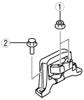
1. Tighten the No.3 engine mount installation stud bolts.
am3zzw00001733
|
2. Secure the engine and the transaxle using an engine jack and attachment.
am3zzw00000622
|
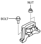
3. Install the No.3 engine mount, and then temporarily tighten the installation bolts and nuts.
am3zzw00012494
|
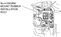
4. Temporarily tighten the No.4 engine mount rubber installation bolt shown in the figure.
am3zzw00012262
|
5. Install the No.1 engine mount rubber and the front crossmember component as a single unit. (See FRONT CROSSMEMBER REMOVAL/INSTALLATION [MZR 1.5, MZR 1.6, MZR 2.0, MZR 2.3 DISI Turbo, MZR 2.5, MZ-CD 1.6].)
6. Temporarily tighten bolts in the order shown in the figure.
am3zzw00012263
|
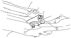
7. Tighten the No.3 engine mount installation bolts and nuts in the order shown in the figure.
am3zzw00009063
|
8. Tighten the No.4 engine mount rubber installation bolt shown in the figure.
am3zzw00012262
|
9. Tighten the No.1 engine mount rubber installation bolts in the order shown in the figure.
am3zzw00012263
|