 |
am3zzw00012526
EXHAUST SYSTEM REMOVAL/INSTALLATION [SKYACTIV-G 2.0]
id0115z5800200
1. Remove the battery cover. (See BATTERY REMOVAL/INSTALLATION [SKYACTIV-G 2.0].)
2. Disconnect the negative battery cable. (See BATTERY REMOVAL/INSTALLATION [SKYACTIV-G 2.0].)
3. Remove the plug hole plate. (See PLUG HOLE PLATE REMOVAL/INSTALLATION [SKYACTIV-G 2.0].)
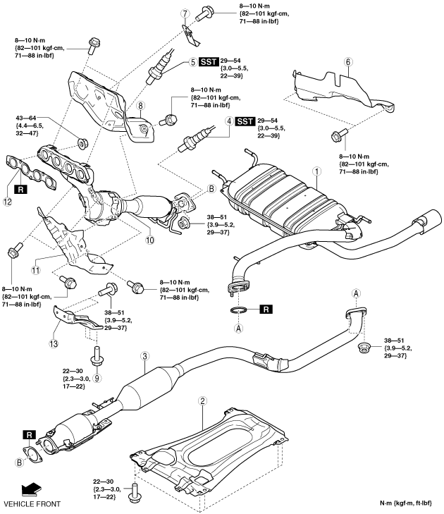
4. Remove in the order indicated in the table.
5. Remove the insulator. (See Exhaust System Insulator Removal/installation Note.)
6. Install in the reverse order of removal.
am3zzw00012526
|
|
1
|
Main silencer
|
|
2
|
Brace bar
|
|
3
|
TWC
|
|
4
|
HO2S
|
|
5
|
A/F sensor
|
|
6
|
insulator
(See Insulator Removal Note.)
|
|
7
|
Clip
|
|
8
|
Exhaust manifold insulator (upper)
|
|
9
|
Exhaust manifold bracket installation bolt
|
|
10
|
Exhaust manifold (WU-TWC)
|
|
11
|
Exhaust manifold insulator (lower)
|
|
12
|
Exhaust manifold gasket
|
|
13
|
Exhaust manifold bracket
|
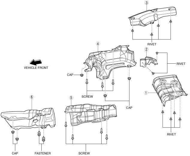
Exhaust System Insulator Removal/installation Note
1. Remove the exhaust system insulator in the order shown in the figure.
2. Install in the reverse order of removal.
am3uuw00008557
|
|
1
|
Insulator (rear No.1)
|
|
2
|
Insulator (rear No.2)
|
|
3
|
Insulator (rear No.3)
|
|
4
|
Insulator (middle No.1)
|
|
5
|
Insulator (middle No.2)
|
|
6
|
Insulator (front)
|
Insulator (Rear No.1, No.2, No.3) Removal Note
1. Push out the mandrel using a hammer and punch (2—2.8 mm {0.08—0.11 in} diameter).
am3uuw00008350
|
2. Remove the flange using a drill (5 mm {0.20 in} drill bit).
am3uuw00008351
|
Insulator Removal Note
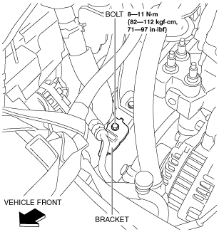
Exhaust Manifold Insulator (Upper) Removal Note
1. Remove the bolt as shown in the figure.
am3zzw00012633
|
2. Set the coolant reserve tank aside with the hose connected.
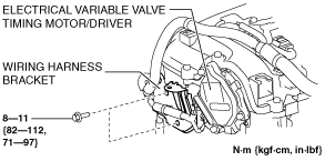
3. Remove the wiring harness bracket shown in the figure.
am3zzw00012527
|
4. Remove the bolt shown in the figure and set the bracket aside.
am3zzw00012633
|
5. Remove the aerodynamic under cover No.2. (See AERODYNAMIC UNDER COVER NO.2 REMOVAL/INSTALLATION.)
6. Remove the No.1 engine mount rubber installation bolt. (See ENGINE REMOVAL/INSTALLATION [SKYACTIV-G 2.0].)
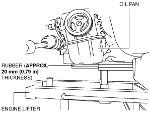
7. Before removing the No.3 engine mount installation bolts, support the engine (oil pan) using a commercially available engine lifter or garage jack.
am3zzw00012528
|
8. Remove the No.3 engine mount installation bolt (frame side). (See ENGINE REMOVAL/INSTALLATION [SKYACTIV-G 2.0].)
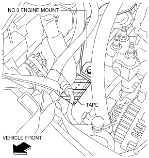
9. Cover the frame with tape.
am3zzw00012529
|
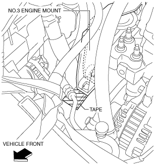
10. Move the engine towards the vehicle front referring to the movement of the No.3 engine mount.
am3zzw00012530
|
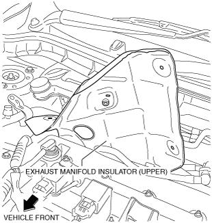
11. Remove the exhaust manifold insulator (upper) as shown in the figure.
am3zzw00012531
|
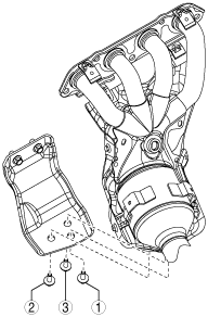
Exhaust Manifold Bracket Installation Bolt Removal Note
1. Remove the aerodynamic under cover No.2. (See AERODYNAMIC UNDER COVER NO.2 REMOVAL/INSTALLATION.)
2. Remove the exhaust manifold bracket installation bolt.
Exhaust Manifold Removal Note
1. Remove the exhaust manifold insulator (upper) installation bolt.
2. Remove the front crossmember. (See FRONT CROSSMEMBER REMOVAL/INSTALLATION [MZR 2.0 DISI i-stop, SKYACTIV-G 2.0].)
3. Remove the exhaust manifold insulator (upper).
4. Remove the exhaust manifold.
Exhaust Manifold Installation Note
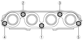
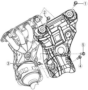
1. Temporarily tighten the exhaust manifold installation nuts (1) and (2) shown in the figure by hand.
am3zzw00013304
|
2. Tighten the exhaust manifold installation nuts (1) and (2) shown in the figure to 33—53 N·m.
3. Temporarily tighten the exhaust manifold installation nuts (3) to (5) shown in the figure by hand.
4. Tighten the exhaust manifold installation nuts (3) to (5) shown in the figure.
5. Tighten the exhaust manifold installation nuts (1) and (2) shown in the figure.
Exhaust Manifold Bracket Installation Bolt Installation Note
1. Tighten the exhaust manifold bracket installation bolt in the order shown in the figure.
am3zzw00013303
|
Exhaust Manifold Insulator (Upper) Installation Note
1. Temporarily tighten the exhaust manifold insulator (upper).
2. Tighten the exhaust manifold insulator in the order shown in the figure (upper).
am3uuw00007297
|