 |
am3zzw00011066
DTC B1884, B1890
id080200801600
System Malfunction Location
|
DTC |
System Malfunction Location |
|---|---|
|
M-MDS display |
|
|
B1884
|
Passenger air bag deactivation (PAD) indicator circuit open or short to body ground
|
|
B1890
|
Passenger air bag deactivation (PAD) indicator circuit short to power supply
|
Detection Condition
Possible Causes
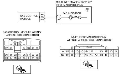
System Wiring Diagram
am3zzw00011066
|
Diagnostic Procedure
|
Step |
Inspection |
Action |
|
|---|---|---|---|
|
1
|
PERFORM MULTI INFORMATION DISPLAY/INFORMATION DISPLAY DTC INSPECTION
• Perform the DTC inspection for the multi information display/information display using the M-MDS.
• Is DTC B1318 displayed?
|
Yes
|
Perform troubleshooting according to corresponding DTC inspection.
|
|
No
|
Go to the next step.
|
||
|
2
|
INSPECT MULTI INFORMATION DISPLAY/INFORMATION DISPLAY CONNECTOR
• Switch the ignition to off.
• Disconnect the negative battery cable and wait for 1 min or more.
• Remove the center panel. (See CENTER PANEL REMOVAL/INSTALLATION.)
• Disconnect the multi information display/information display connector.
• Inspect the multi information display/information display connector. (Corrosion, damage, and disconnected pins)
• Is there any malfunction?
|
Yes
|
Repair the multi information display/information display wiring harness.
|
|
No
|
Go to the next step.
|
||
|
3
|
INSPECT PAD INDICATOR
• Remove the console. (See CONSOLE REMOVAL/INSTALLATION.)
• Disconnect all SAS control module connectors. (See SAS CONTROL MODULE REMOVAL/INSTALLATION.)
• Connect the multi information display/information display connector.
• Ground multi information display/information display connector terminal 1H using a jumper wire.
• Connect the negative battery cable.
• Switch the ignition to ON.
• Does the PAD indicator illuminate?
|
Yes
|
Go to the next step.
|
|
No
|
Replace the multi information display/information display.
|
||
|
4
|
INSPECT WIRING HARNESS BETWEEN MULTI INFORMATION DISPLAY/INFORMATION DISPLAY AND SAS CONTROL MODULE
• Switch the ignition to off.
• Disconnect the negative battery cable and wait for 1 min or more.
• Remove the column cover. (See COLUMN COVER REMOVAL/INSTALLATION.)
• Disconnect the clock spring connector.
• Remove the glove compartment. (See GLOVE COMPARTMENT REMOVAL/INSTALLATION.)
• Disconnect the passenger-side air bag module connector. (See PASSENGER-SIDE AIR BAG MODULE REMOVAL/INSTALLATION.)
• Disconnect the passenger-side front seat connector. (See FRONT SEAT REMOVAL/INSTALLATION.)
• Remove the C-pillar trim. (See C-PILLAR TRIM REMOVAL/INSTALLATION.)
• Disconnect the driver and passenger-side curtain air bag module connector (harness side). (See CURTAIN AIR BAG MODULE REMOVAL/INSTALLATION.)
• Remove the B-pillar lower trim. (See B-PILLAR LOWER TRIM REMOVAL/INSTALLATION.)
• Disconnect the lap pre-tensioner seat belt connector. (See FRONT SEAT BELT REMOVAL/INSTALLATION.)
• Disconnect the driver and passenger-side pre-tensioner seat belt connector. (See FRONT SEAT BELT REMOVAL/INSTALLATION.)
• Inspect the wiring harness between multi information display/information display connector terminal 1H and SAS control module connector terminal 3B for the following:
• Is the wiring harness normal?
|
Yes
|
Go to the next step.
|
|
No
|
Repair the wiring harness between the multi information display/information display and SAS control module.
|
||
|
5
|
INSPECT THE WIRING HARNESS BETWEEN SAS CONTROL MODULE AND MULTI INFORMATION DISPLAY/INFORMATION DISPLAY FOR A SHORT CIRCUIT TO THE POWER SUPPLY
• Connect the negative battery cable.
• Switch the ignition to ON.
• Measure the voltage of SAS control module connector terminal 3B.
• Is the voltage measured?
|
Yes
|
Repair the wiring harness between the multi information display/information display and SAS control module.
|
|
No
|
Go to the next step.
|
||
|
6
|
PERFORM SAS CONTROL MODULE DTC INSPECTION
• Switch the ignition to off.
• Disconnect the negative battery cable and wait for 1min or more.
• Reconnect all disconnected connectors.
• Connect the negative battery cable.
• Switch the ignition to ON.
• Clear the DTC for the SAS control module using the M-MDS. (See CLEARING DTC.)
• Perform the DTC inspection for the SAS control module using the M-MDS. (See DTC INSPECTION.)
• Are the same DTCs present?
|
Yes
|
Replace the SAS control module.
|
|
No
|
DTC troubleshooting completed.
|
||