1. Disconnect the negative battery cable.
2. Detach the bonnet release lever from the lower panel. (See BONNET LATCH AND RELEASE LEVER REMOVAL/INSTALLATION.)
3. Remove the front scuff plate. (See FRONT SCUFF PLATE REMOVAL/INSTALLATION.)
4. Remove the front side trim. (See FRONT SIDE TRIM REMOVAL/INSTALLATION.)
5. Remove the lower panel. (See LOWER PANEL REMOVAL/INSTALLATION.)
6. Remove the shower duct (LH).
7. Remove the airflow mode actuator. (full-auto air conditioner) (See AIRFLOW MODE ACTUATOR REMOVAL/INSTALLATION.)
8. Disconnect the airflow mode wire. (manual air conditioner) (See CLIMATE CONTROL UNIT REMOVAL [MANUAL AIR CONDITIONER].)
9. Remove the airflow mode rod (1).
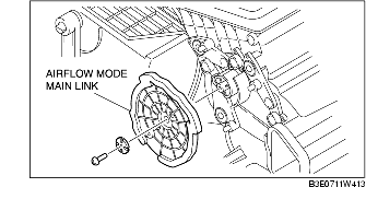
10. Remove the airflow mode main link.
11. Install in the reverse order of removal.
12. Adjust the airflow mode wire. (manual air conditioner) (See CLIMATE CONTROL UNIT WIRE ADJUSTMENT.)
1. Disconnect the negative battery cable.
2. Removal the following parts.
3. Remove the airflow mode rot (1).
4. Remove the airflow mode main rink.
5. Install in the reverse order of removal.
6. Adjust the airflow mode wire. (manual air conditioner) (See CLIMATE CONTROL UNIT WIRE ADJUSTMENT.)
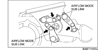
1. Push and hold each airflow mode sub link in the direction of the arrow.
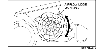
2. Set the airflow mode main link to the A/C unit as shown in the figure.
3. Press the airflow mode main link lightly to the A/C unit it in the direction shown by the arrow, then set the projections of each airflow mode sub link into the grooves of the airflow mode main link.
4. Rotate airflow mode main link and verify that each mode is accessed properly.