A/C UNIT REMOVAL/INSTALLATION
id071100800200
Replacement Part
|
O-ring (cooler hose (LO))
Quantity: 1
Location of use: A/C unit
|
O-ring (cooler pipe)
Quantity: 1
Location of use: A/C unit
|
-
Warning
-
• Handling the air bag module improperly can accidentally deploy the air bag module, which may seriously injure you. Read the air bag system service warnings and cautions before handling the air bag module.
-
Caution
-
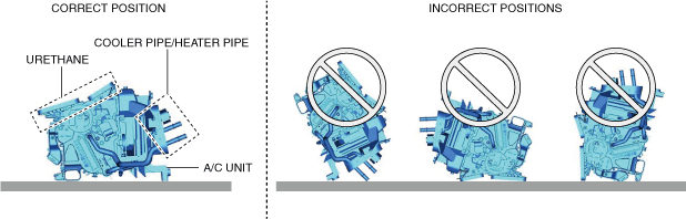
• When leaving the A/C unit, store it in the correct position shown in the figure. If the A/C unit is left in an incorrect position, the cooler pipe, heater pipe, or urethane could be deformed or damaged.
-
Note
-
• When removing the driver-side air bag module, it is necessary to rotate the steering wheel. If the ignition has been switched off with the driver's door closed, the steering wheel will be locked. Perform the procedure from Steps 1-3 so that the steering wheel will not be locked.
1. Switch the ignition ON (engine off or on).
2. Open the driver's door.
3. Switch the ignition off.
4. Disconnect the negative battery terminal. (See NEGATIVE BATTERY TERMINAL DISCONNECTION/CONNECTION.)
5. Discharge the refrigerant. (See REFRIGERANT RECOVERY.) (See REFRIGERANT CHARGING.)
6. Drain the engine coolant. (See ENGINE COOLANT REPLACEMENT [SKYACTIV-G 2.0, SKYACTIV-G 2.5 (WITHOUT CYLINDER DEACTIVATION)].) (See ENGINE COOLANT REPLACEMENT [SKYACTIV-G 2.5 (WITH CYLINDER DEACTIVATION)].) (See ENGINE COOLANT REPLACEMENT [SKYACTIV-G 2.5T].) (See ENGINE COOLANT REPLACEMENT [SKYACTIV-D 2.2].)
7. Remove the following parts:
- (1) Plug hole plate (SKYACTIV-G 2.0, SKYACTIV-G 2.5, SKYACTIV-G 2.5T) (See PLUG HOLE PLATE REMOVAL/INSTALLATION [SKYACTIV-G 2.5 (WITH CYLINDER DEACTIVATION)].) (See PLUG HOLE PLATE REMOVAL/INSTALLATION [SKYACTIV-G 2.0, SKYACTIV-G 2.5 (WITHOUT CYLINDER DEACTIVATION)].) (See PLUG HOLE PLATE REMOVAL/INSTALLATION [SKYACTIV-G 2.5T].)
-
- (2) Engine cover (SKYACTIV-D 2.2) (See ENGINE COVER REMOVAL/INSTALLATION [SKYACTIV-D 2.2].)
-
- (3) Windshield wiper arm and blade (See WINDSHIELD WIPER ARM AND BLADE REMOVAL/INSTALLATION.)
-
- (4) Cowl grille (See COWL GRILLE REMOVAL/INSTALLATION.)
-
- (5) Front scuff plate (See FRONT SCUFF PLATE REMOVAL/INSTALLATION.)
-
- (6) Front side trim (See FRONT SIDE TRIM REMOVAL/INSTALLATION.)
-
- (7) A-pillar trim (See A-PILLAR TRIM REMOVAL/INSTALLATION.)
-
- (8) Meter hood cover (See METER HOOD COVER REMOVAL/INSTALLATION.)
-
- (9) Audio panel (See AUDIO PANEL REMOVAL/INSTALLATION.)
-
- (10) Passenger-side decoration panel (See DECORATION PANEL REMOVAL/INSTALLATION.)
-
- (11) Center panel (See CENTER PANEL REMOVAL/INSTALLATION.)
-
- (12) Driver-side decoration panel (See DECORATION PANEL REMOVAL/INSTALLATION.)
-
- (13) Upper column cover (See COLUMN COVER REMOVAL/INSTALLATION.)
-
- (14) Meter hood No.1 (See METER HOOD REMOVAL/INSTALLATION.)
-
- (15) Lower column cover (See COLUMN COVER REMOVAL/INSTALLATION.)
-
- (16) Instrument cluster (See INSTRUMENT CLUSTER REMOVAL/INSTALLATION.)
-
- (17) Center display (See CENTER DISPLAY REMOVAL/INSTALLATION.)
-
- (18) Bonnet release lever (See BONNET LATCH AND RELEASE LEVER REMOVAL/INSTALLATION.)
-
- (19) Fuel-filler lid opener lever (See FUEL-FILLER LID OPENER AND LEVER REMOVAL/INSTALLATION.)
-
- (20) Driver-side lower panel (See LOWER PANEL REMOVAL/INSTALLATION.)
-
- (21) Driver-side air bag module (See DRIVER-SIDE AIR BAG MODULE REMOVAL [TWO-STEP DEPLOYMENT CONTROL SYSTEM].) (See DRIVER-SIDE AIR BAG MODULE INSTALLATION [TWO-STEP DEPLOYMENT CONTROL SYSTEM].) (See DRIVER-SIDE AIR BAG MODULE REMOVAL [STANDARD DEPLOYMENT CONTROL SYSTEM].) (See DRIVER-SIDE AIR BAG MODULE INSTALLATION [STANDARD DEPLOYMENT CONTROL SYSTEM].)
-
- (22) Steering wheel (See STEERING WHEEL AND COLUMN REMOVAL/INSTALLATION.)
-
- (23) Joint cover (See STEERING WHEEL AND COLUMN REMOVAL/INSTALLATION.)
-
- (24) Steering shaft (See STEERING WHEEL AND COLUMN REMOVAL/INSTALLATION.)
-
- (25) Glove compartment (See GLOVE COMPARTMENT REMOVAL/INSTALLATION.)
-
- (26) Dashboard under cover (See DASHBOARD UNDER COVER REMOVAL/INSTALLATION.)
-
- (27) Passenger-side lower panel (See LOWER PANEL REMOVAL/INSTALLATION.)
-
- (28) Side wall (See SIDE WALL REMOVAL/INSTALLATION.)
-
- (29) Selector lever knob (ATX) (See AUTOMATIC TRANSAXLE SHIFT MECHANISM REMOVAL/INSTALLATION.)
-
- (30) Shift lever knob (MTX) (See MANUAL TRANSAXLE SHIFT MECHANISM REMOVAL/INSTALLATION [C66M-R].)
-
- (31) Shift panel (See SHIFT PANEL REMOVAL/INSTALLATION.)
-
- (32) Front console box (See FRONT CONSOLE BOX REMOVAL/INSTALLATION.)
-
- (33) Rear console component (See REAR CONSOLE REMOVAL/INSTALLATION.)
-
- (34) Center lower panel (See LOWER PANEL REMOVAL/INSTALLATION.)
-
- (35) Climate control unit (See CLIMATE CONTROL UNIT REMOVAL/INSTALLATION.)
-
- (36) Selector lever component (ATX) (See AUTOMATIC TRANSAXLE SHIFT MECHANISM REMOVAL/INSTALLATION.)
-
- (37) Shift lever component (MTX) (See MANUAL TRANSAXLE SHIFT MECHANISM REMOVAL/INSTALLATION [C66M-R].)
-
- (38) Rear vent duct (with rear vent duct) (See REAR VENT DUCT REMOVAL/INSTALLATION.)
-
- (39) Electric parking brake control module (See ELECTRIC PARKING BRAKE CONTROL MODULE REMOVAL/INSTALLATION.)
-
- (40) Electric parking brake control module bracket (See SAS CONTROL MODULE REMOVAL/INSTALLATION [STANDARD DEPLOYMENT CONTROL SYSTEM].) (See SAS CONTROL MODULE REMOVAL/INSTALLATION [TWO-STEP DEPLOYMENT CONTROL SYSTEM].)
-
- (41) Dashboard (See DASHBOARD REMOVAL/INSTALLATION.)
-
- (42) Front heat duct (See FRONT HEAT DUCT REMOVAL/INSTALLATION.)
-
- (43) Blower unit (See BLOWER UNIT REMOVAL/INSTALLATION.)
-
- (44) Foot support (See FOOT SUPPORT REMOVAL/INSTALLATION.)
-
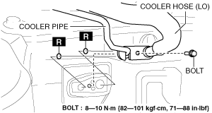
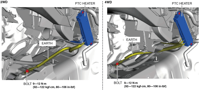
8. Remove the bolt.
-
Caution
-
• If moisture or foreign matter enters the refrigeration cycle, cooling ability will be lowered and abnormal noise or other malfunctions could occur. Always plug open fittings immediately after removing any refrigeration cycle parts.
9. Disconnect the cooler hose (LO) and cooler pipe.
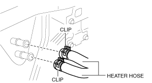
10. Disconnect the heater hose.
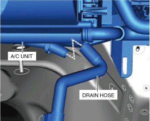
11. Disconnect the drain hose.
12. Remove the bolt. (with PTC heater)
13. Disconnect the earth. (with PTC heater)
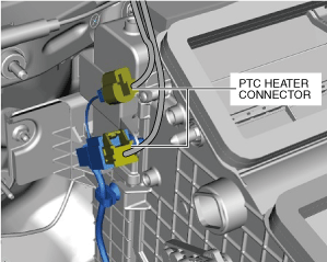
14. Disconnect the PTC heater connectors. (with PTC heater)
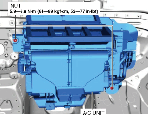
15. Remove the nuts.
16. Remove the A/C unit. Do not allow compressor oil to spill.
17. Install in the reverse order of removal. (See A/C Unit Installation Note.) (See Drain Hose Installation Note.)
18. Inspect for engine coolant leakage. (See ENGINE COOLANT LEAKAGE INSPECTION [SKYACTIV-G 2.0, SKYACTIV-G 2.5 (WITHOUT CYLINDER DEACTIVATION)].) (See ENGINE COOLANT LEAKAGE INSPECTION [SKYACTIV-G 2.5 (WITH CYLINDER DEACTIVATION)].) (See ENGINE COOLANT LEAKAGE INSPECTION [SKYACTIV-G 2.5T].) (See ENGINE COOLANT LEAKAGE INSPECTION [SKYACTIV-D 2.2].)
19. Perform the refrigerant system performance test. (See REFRIGERANT SYSTEM PERFORMANCE TEST.)
A/C Unit Installation Note
1. When replacing the A/C unit or evaporator, add compressor oil to the refrigerant cycle.
-
Supplemental oil amount (approx. quantity)
-
40 ml {40 cc, 1.4 US fl oz}
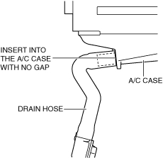
Drain Hose Installation Note
1. Install the drain hose as shown in the figure.