Note
- The pressure limiter opens when the fuel pressure has become excessively high due to intermittent sticking of the FRP regulator.
- If the vehicle runs out of fuel, air may be entered in the fuel system. When there is air in the fuel piping, the smooth flow of fuel into the fuel supply pump is interrupted and this DTC may be set. Bleed air from the fuel piping after refilling.
1. Engine control system check
Refer to "51.Engine Control 1A.Troubleshooting(RZ4E-TC) Diagnostic system check-engine controls".
2. Prioritized DTC check
1) Connect the scan tool.
2) Turn OFF the ignition switch for 30 seconds or more.
3) Start the engine.
4) Observe the DTC information with a scan tool. Is DTC P0088, P0089, P0091, P0092, P0192, P0193, P0201, P0202, P0203, P0204, P2146, or P2149 set at the same time?
Yes
Go to the applicable DTC diagnosis.
Refer to "51.Engine Control 1A.Troubleshooting(RZ4E-TC) DTC P0089 (Flash Code 151) Fuel Pressure Regulator Performance".
Refer to "51.Engine Control 1A.Troubleshooting(RZ4E-TC) DTC P0201 (Flash Code 271) Injector Circuit - Cylinder 1".
Refer to "51.Engine Control 1A.Troubleshooting(RZ4E-TC) DTC P0202 (Flash Code 272) Injector Circuit - Cylinder 2".
Refer to "51.Engine Control 1A.Troubleshooting(RZ4E-TC) DTC P0203 (Flash Code 273) Injector Circuit - Cylinder 3".
Refer to "51.Engine Control 1A.Troubleshooting(RZ4E-TC) DTC P0204 (Flash Code 274) Injector Circuit - Cylinder 4".
No
=>Go to DTC check when revving engine.
3. DTC check when revving engine
1) Turn OFF the ignition switch.
2) Set the shift lever to the neutral position and apply the parking brake.
3) Start the engine.
4) While observing the DTC information with a scan tool, depress the accelerator pedal from idle to full throttle several times. Is a DTC set?
Yes
=>Go to FRP sensor signal voltage check.
No
An intermittent problem due to foreign object in the fuel can be suspected.
Replace the fuel filter element.
Refer to "1.Engine 1C.Fuel System(RZ4E-TC) fuel filter element removal".
Refer to "1.Engine 1C.Fuel System(RZ4E-TC) fuel filter element installation".
4. FRP sensor signal voltage check
1) Turn OFF the ignition switch.
2) Wait for 30 seconds to reduce the fuel pressure of the fuel rail.
3) Turn ON the ignition switch.
4) Observe the Fuel Rail Pressure (FRP) Sensor parameter on the scan tool. Is the Fuel Rail Pressure (FRP) Sensor parameter within the specified range?
Value: 0.9 to 1.0 V
Yes
No
=>Go to FRP sensor circuit inspection.
5. Injector inspection
1) Start the engine.
2) Perform the Cylinder Balance with a scan tool.
3) Command each injector OFF and verify the engine speed changes for each injector. Are there any injectors that do not change the engine speed when commanded OFF?
Yes
Replace the injectors that do not change.
Note
- If an injector has been replaced, be sure to set the Injector ID Code on the ECM.
Refer to "1.Engine 1C.Fuel System(RZ4E-TC) injector removal".
Refer to "1.Engine 1C.Fuel System(RZ4E-TC) injector installation".
No
=>Go to Fuel leakage inspection.
6. Fuel leakage inspection
1) Inspect that the fuel piping between the fuel tank and the fuel supply pump is properly connected, there are no cuts or cracks in the fuel hoses, and proper clamps are used. Is the result normal?
Note
- The fuel piping between the fuel tank and the fuel supply pump is slightly vacuumed when the engine is running. Therefore, if the piping is not connected securely, air can get inside. If the engine speed or the engine load increases while air is in the fuel system, fluctuation in the fuel rail pressure occurs, and this DTC may be set.
2) Start the engine.
3) Check the high-pressure side of the fuel system and inspect for a fuel leakage between the fuel supply pump and the fuel rail. Is the result normal?
Note
- Check for fuel leakage from the high pressure piping inlet to the bottom of the cylinder head cover. If a fuel leakage exists, the engine oil level will rise. Inspect the engine oil for fuel contamination.
4) Are all of the results normal?
Yes
=>Go to Suction side fuel piping inspection.
No
Repair the fuel leakage as necessary.
7. Suction side fuel piping inspection
1) Turn OFF the ignition switch.
2) Disconnect the fuel feed hose from the fuel supply pump.
Note
- Use a pan to collect the fuel that has leaked from the disconnected fuel feed hose.
3) Connect the vacuum pump to the fuel feed hose.
Note
- The vacuum pump must be cleaned before connecting to the fuel piping. The fuel supply pump may be damaged due to the foreign material that has intruded into the connection hose.
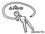
SST: 5-8840-0279-0 - vacuum pump
4) Operate the vacuum pump and inspect for fuel smooth flow. Is the result normal?
Caution
- Take care that no fuel enters the vacuum pump.
Note
- If there is a leakage or restriction in the suction side, the smooth flow of fuel may be interrupted due to fuel leakage, fuel filter element clogging, twisting or collapsing of the fuel hose or pipe, etc. Also, foreign material in the fuel tank may enter the fuel piping.
Yes
=>Go to Inspection for air bubble intrusion.
No
Repair the fuel piping between the fuel tank and the fuel supply pump.
8. Inspection for air bubble intrusion
1) Replace the fuel hose between the fuel supply pump and the fuel filter with a clear hose.
2) Bleed the air from the fuel piping.
3) Start the engine.
4) Allow the engine to idle for at least 1 minute.
5) Inspect the fuel in the clear hose for air bubble intrusion while holding the engine speed at 3,000 rpm or more for at least 1 minute. Is the result normal?
6) Inspect that the fuel piping between the fuel tank and the fuel supply pump is properly connected, there are no cuts or cracks in the fuel hoses, and proper clamps are used. Is the result normal?
7) Are all of the results normal?
Yes
=>Go to Fuel supply pump suction check.
No
Repair the fuel piping between the fuel tank and the fuel supply pump.
9. Fuel supply pump suction check
1) Connect the fuel feed hose to the fuel supply pump.
2) Disconnect all the injector harness connectors (E12, E13, E14, and E15) in order to disable the fuel injection.
Refer to "RHD Engine Control (RZ4E)" in the ETM (wiring diagram). (Open using the ETM viewer.).
Refer to "LHD Engine Control (RZ4E)" in the ETM (wiring diagram). (Open using the ETM viewer.).
3) Disconnect the fuel feed hose from the fuel tank.
Note
- Use a pan to collect the fuel that has leaked from the disconnected fuel feed hose.
4) Connect the vacuum pump to the fuel feed hose. Make sure that the connection between the vacuum pump and the fuel feed hose is secured.
SST: 5-8840-0279-0 - vacuum pump
Note
- The vacuum pump must be cleaned before connecting to the fuel piping.
5) Crank 3 times while monitoring the vacuum pump gauge. Can a vacuum of the specified value be drawn?
Caution
- Cranking should be performed within 5 seconds at a time, and should not exceed 15 seconds in total.
Value: -8.5 kPa { 2.5 inHg }
Caution
- If it is likely that the vacuum will show the specified value or more, stop cranking immediately.
Yes
=>Go to FRP regulator circuit inspection.
No
Repair the fuel piping between the fuel supply pump and the fuel rail
10. FRP regulator circuit inspection
1) Inspect for poor connections at the FRP regulator harness connector (pins 1 and 2 of E52). Is the connection status normal?
2) Inspect for poor connections at the ECM harness connector (pins 8, 16, 24, and 32 of E4). Is the connection status normal?
3) Inspect the circuit between the ECM (pins 8, 16, 24, and 32 of E4) and the FRP regulator (pins 1 and 2 of E52) for high resistance. Is the result normal?
Refer to "RHD Engine Control (RZ4E)" in the ETM (wiring diagram). (Open using the ETM viewer.).
Refer to "LHD Engine Control (RZ4E)" in the ETM (wiring diagram). (Open using the ETM viewer.).
4) Are all of the results normal?
Yes
Replace the fuel supply pump and the fuel filter element.
Note
- The fuel supply pump must be timed with the engine, and the ECM requires learning.
Refer to "1.Engine 1C.Fuel System(RZ4E-TC) fuel supply pump removal".
Refer to "1.Engine 1C.Fuel System(RZ4E-TC) fuel supply pump installation".
Caution
- If the fuel supply pump is replaced, replace the fuel filter element at the same time.
Refer to "1.Engine 1C.Fuel System(RZ4E-TC) fuel filter element removal".
Refer to "1.Engine 1C.Fuel System(RZ4E-TC) fuel filter element installation".
No
Repair the circuit or connection as necessary.
11. FRP sensor circuit inspection
1) Inspect for poor connections at the FRP sensor harness connector (pins 1, 2, and 3 of E47). Is the connection status normal?
2) Inspect for poor connections at the ECM harness connector (pins 1, 6, 9, and 20 of E4). Is the connection status normal?
3) Inspect the circuit between the ECM (pins 1, 6, 9, and 20 of E4) and the FRP sensor (pins 1, 2, and 3 of E47) for high resistance. Is the result normal?
Refer to "RHD Engine Control (RZ4E)" in the ETM (wiring diagram). (Open using the ETM viewer.).
Refer to "LHD Engine Control (RZ4E)" in the ETM (wiring diagram). (Open using the ETM viewer.).
4) Are all of the results normal?
Yes
Replace the FRP sensor.
Refer to "1.Engine 1Z.Engine Electrical Control(RZ4E-TC) FRP sensor removal".
Refer to "1.Engine 1Z.Engine Electrical Control(RZ4E-TC) FRP sensor installation".
No
Repair the circuit or connection as necessary.
12. Repair verification
1) Clear the DTC with a scan tool.
2) Turn OFF the ignition switch for 30 seconds or more.
3) Start the engine.
4) Operate the vehicle under the conditions for running the DTC.
5) Observe the DTC information with a scan tool.