 |
ac5wzw00005222
CYLINDER HEAD GASKET REPLACEMENT [SKYACTIV-D 2.2]
id0110s5800700
Replacement Part
|
O-ring (Fuel injector 2pin type)
Quantity: 1
Location of use: Rear camshaft cap
|
Gasket
Quantity: 2
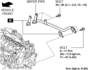
Location of use: Water pipe
|
Cylinder head gasket
Quantity: 1
Location of use: Cylinder head
|
Oil and Chemical Type
|
Engine oil
Type: Recommended oil
|
Gear oil
Type: SAE 90 gear oil or equivalent
|
Sealant
Type: Loctite #962T or equivalent
|
1. Disconnect the negative battery terminal. (See NEGATIVE BATTERY TERMINAL DISCONNECTION/CONNECTION.)
2. Remove the engine cover. (See ENGINE COVER REMOVAL/INSTALLATION [SKYACTIV-D 2.2].)
3. Remove the fuel injectors. (See FUEL INJECTOR REMOVAL/INSTALLATION [SKYACTIV-D 2.2].)
4. Remove the front under cover No.2. (See FRONT UNDER COVER No.2 REMOVAL/INSTALLATION.)
5. Remove the front splash shield (RH). (See SPLASH SHIELD REMOVAL/INSTALLATION.)
6. Remove the drive belt. (See DRIVE BELT REMOVAL/INSTALLATION [SKYACTIV-D 2.2].)
7. Drain the engine oil. (See ENGINE OIL REPLACEMENT [SKYACTIV-D 2.2].)
8. Drain the engine coolant. (See ENGINE COOLANT REPLACEMENT [SKYACTIV-D 2.2].)
9. Disconnect the upper radiator hose.
10. Remove the intake manifold. (See INTAKE-AIR SYSTEM REMOVAL/INSTALLATION [SKYACTIV-D 2.2].)
11. Remove the transfer bracket and transfer. (See TRANSFER REMOVAL/INSTALLATION [GW6AX-EL (SKYACTIV-D 2.2)] (ATX).)
(See TRANSFER REMOVAL/INSTALLATION [D66MX-R] (MTX).)
12. Disconnect the catalytic converter from the middle pipe, and remove the catalytic converter. (See EXHAUST SYSTEM REMOVAL/INSTALLATION [SKYACTIV-D 2.2].)
13. Remove the turbocharger. (See TURBOCHARGER REMOVAL/INSTALLATION [SKYACTIV-D 2.2].)
14. Remove the exhaust gas temperature sensor No.1. (See EXHAUST GAS TEMPERATURE SENSOR REMOVAL/INSTALLATION [SKYACTIV-D 2.2].)
15. Remove the exhaust gas pressure sensor No.1 component. (See EXHAUST GAS PRESSURE SENSOR REMOVAL/INSTALLATION [SKYACTIV-D 2.2].)
16. Remove the exhaust manifold. (See EXHAUST SYSTEM REMOVAL/INSTALLATION [SKYACTIV-D 2.2].)
17. Remove the lower case. (See LOWER CASE REMOVAL/INSTALLATION [SKYACTIV-D 2.2].)
18. Remove the vacuum pump. (See VACUUM PUMP REMOVAL/INSTALLATION [SKYACTIV-D 2.2].)
19. Remove the supply pump. (See SUPPLY PUMP REMOVAL/INSTALLATION [SKYACTIV-D 2.2].)
20. Remove the CMP sensor. (See CAMSHAFT POSITION (CMP) SENSOR REMOVAL/INSTALLATION [SKYACTIV-D 2.2].)
21. Disconnect the heater hose. (Fuel injector (2pin type))
22. Remove the oil pan. (See OIL PAN REMOVAL/INSTALLATION [SKYACTIV-D 2.2].)
23. Remove the timing chain and chain guide. (See TIMING CHAIN REMOVAL/INSTALLATION [SKYACTIV-D 2.2].)
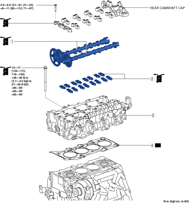
24. Remove in the order indicated in the table.
25. Install in the reverse order of removal.
26. Refill with the specified type and amount of the engine oil. (See ENGINE OIL REPLACEMENT [SKYACTIV-D 2.2].)
27. Refill the engine coolant. (See ENGINE COOLANT REPLACEMENT [SKYACTIV-D 2.2].)
28. Start the engine, and inspect and adjust the following:
Fuel injector (2pin type)
ac5wzw00005222
|
Fuel injector (6pin type)
ac5wzw00011962
|
|
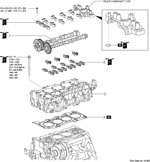
1
|
Camshaft
(See Camshaft Removal Note.)
(See Camshaft Installation Note.)
|
|
2
|
Rocker arm
(See Rocker Arm Removal Note.)
(See Rocker Arm Installation Note.)
|
|
3
|
Cylinder head
(See Cylinder Head Removal Note.)
|
|
4
|
Cylinder head gasket
|
Camshaft Removal Note
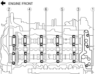
1. Loosen the camshaft cap installation bolts in a few passes in the order shown in the figure and remove the camshaft caps.
ac5wzw00004947
|
2. Remove the camshaft.
Rocker Arm Removal Note
1. Keep the rocker arms in the order of removal to enable reassembly in their original positions.
Cylinder Head Removal Note
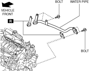
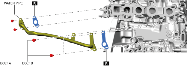
1. Remove the water pipe.
Fuel injector (2pin type)
ac5wzw00009342
|
Fuel injector (6pin type)
ac5wzw00011963
|
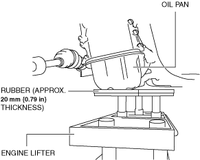
2. Temporarily install the oil pan to support the engine from under the vehicle.
3. Support the engine (oil pan) using a commercially available engine lifter or garage jack.
ac5wzw00009343
|
4. Remove the SST (49 L017 5A0) that suspended the engine and set it aside.
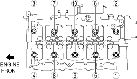
5. Loosen the cylinder head installation bolts in two or three passes in the order shown in the figure and remove them.
ac5wzw00011964
|
6. Remove the cylinder head.
Cylinder Head Installation Note
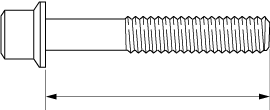
1. Measure the length of the cylinder head bolt.
amxzzw00003984
|
2. When a cylinder head bolt is reused, apply engine oil to any part of the following:
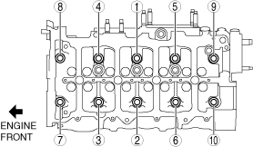
3. Tighten the cylinder head bolts in the order shown in the following 5 steps.
ac5wzw00011965
|
4. Install the SST (49 L017 5A0) which was set aside and secure the engine. (See TIMING CHAIN REMOVAL/INSTALLATION [SKYACTIV-D 2.2].)
5. Remove the engine lifter or garage jack.
6. Remove the temporarily assembled oil pan.
7. Install the water pipe.
Fuel injector (2pin type)
ac5wzw00009344
|
Fuel injector (6pin type)
ac5wzw00011966
|
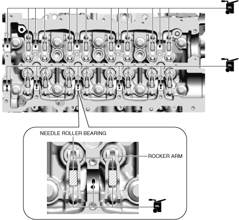
Rocker Arm Installation Note
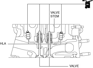
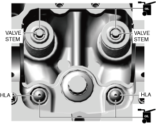
1. Apply engine oil to the HLAs and the end of the valve stems.
Fuel injector (2pin type)
ac5wzw00004952
|
Fuel injector (6pin type)
ac5wzw00011967
|
2. Install the rocker arms to the same positions as before removal.
Camshaft Installation Note
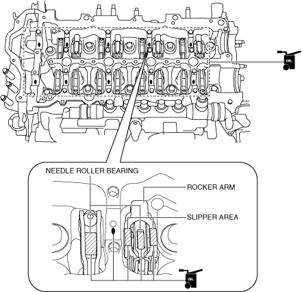
1. Apply gear oil (SAE 90 or equivalent) or engine oil to the following locations.
Fuel injector (2pin type)
ac5wzw00005225
|
Fuel injector (6pin type)
ac5wzw00011968
|
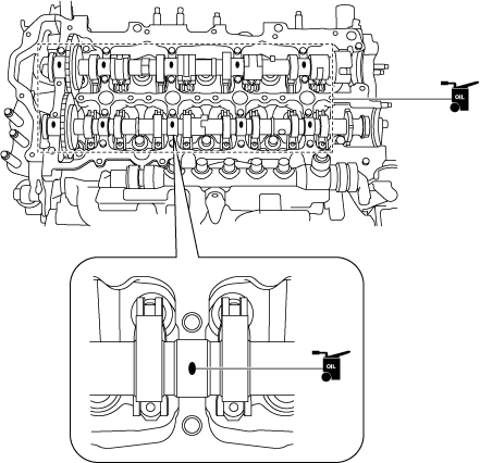
2. Apply gear oil (SAE 90 or equivalent) or engine oil to the following locations of each camshaft. (Fuel injector (2pin type))
3. Apply gear oil (SAE 90 or equivalent) or engine oil to the thrust surface (both surfaces front and back) of the front journal on each camshaft. (Fuel injector (6pin type))
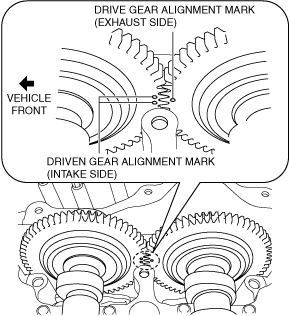
4. Place the camshaft on the cylinder head and align the alignment marks for each gear as shown in the figure.
ac5wzw00009345
|
5. Apply gear oil (SAE 90 or equivalent) or engine oil to the center area of each journal of the camshaft.
Fuel injector (2pin type)
ac5jjw00004506
|
Fuel injector (6pin type)
ac5wzw00011969
|
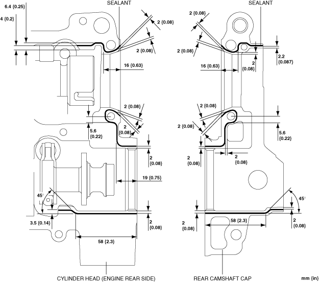
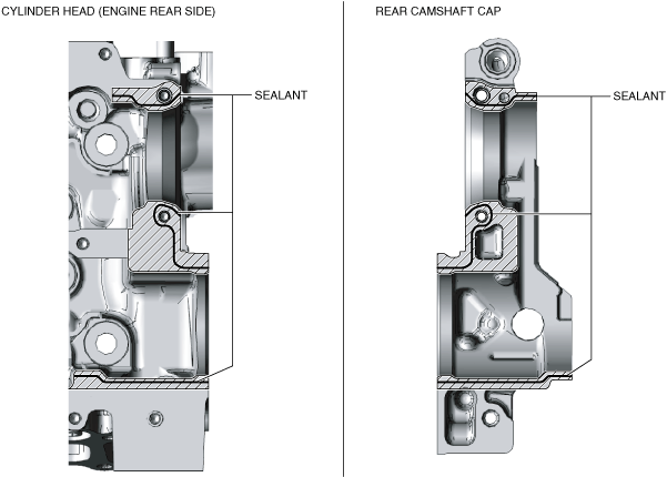
6. Apply sealant agent (Loctite #962T or equivalent) to the rear side of the cylinder head or rear camshaft cap.
Fuel injector (2pin type)
ac5wzw00007250
|
Fuel injector (6pin type)
ac5wzw00011970
|
7. Apply engine oil to the new rear camshaft cap O-ring and install it to the rear camshaft cap.
8. Apply gear oil (SAE 90 or equivalent) or engine oil to the thrust surface of the front camshaft cap.
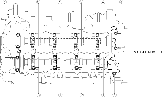
9. Install the camshaft caps in the marked number order, and temporarily tighten the camshaft cap installation bolts in two or three passes evenly.
10. Tighten the camshaft cap installation bolts in two steps in the order shown in the figure.
ac5wzw00004956
|