 |
am3zzw00024893
ENGINE REMOVAL/INSTALLATION [SKYACTIV-G 2.0]
id0110h2950800
Engine Removal
1. Disconnect the negative battery terminal. (See NEGATIVE BATTERY TERMINAL DISCONNECTION/CONNECTION.)
2. Remove the front under cover No.1 and No.2. (See FRONT UNDER COVER No.1 REMOVAL/INSTALLATION.) (See FRONT UNDER COVER No.2 REMOVAL/INSTALLATION.)
3. Remove the front splash shield. (See SPLASH SHIELD REMOVAL/INSTALLATION.)
4. Drain the engine coolant. (See ENGINE COOLANT REPLACEMENT [SKYACTIV-G 2.0].)
5. Drain the ATF. (See AUTOMATIC TRANSAXLE FLUID (ATF) REPLACEMENT [ET6A-EL, ET6AX-EL].)
6. Remove the front wheels and tires. (See WHEEL AND TIRE REMOVAL/INSTALLATION.)
7. Remove the plug hole plate. (See PLUG HOLE PLATE REMOVAL/INSTALLATION [SKYACTIV-G 2.0].)
8. Remove the following parts as a single unit: (See INTAKE-AIR SYSTEM REMOVAL/INSTALLATION [SKYACTIV-G 2.0].)
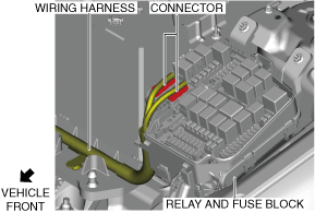
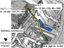
9. Remove the bolts and nut shown in the figure, and set the wiring harness aside.
am3zzw00024893
|
10. Disconnect the connector.
am3zzw00024881
|
11. Remove the battery tray and PCM component. (See BATTERY REMOVAL/INSTALLATION [SKYACTIV-G 2.0].)
12. Disconnect the evaporative hose. (See PURGE SOLENOID VALVE REMOVAL/INSTALLATION [SKYACTIV-G 2.0].)
13. Disconnect the fuel hose. (See QUICK RELEASE CONNECTOR (EMISSION SYSTEM) REMOVAL/INSTALLATION [SKYACTIV-G 2.0].)
14. Disconnect the heater hoses. (See A/C UNIT REMOVAL/INSTALLATION.)
15. Disconnect the upper radiator hose from the engine side.
16. Disconnect the lower radiator hose from the radiator.
17. Disconnect the lower radiator hose clip.
18. Remove the generator drive belt. (See DRIVE BELT REMOVAL/INSTALLATION [SKYACTIV-G 2.0].)
19. Remove the TWC installation nuts (exhaust manifold side) and secure the TWC using wire or rope so that it is out of the way. (2WD) (See EXHAUST SYSTEM REMOVAL/INSTALLATION [SKYACTIV-G 2.0].)
20. Remove the propeller shaft. (AWD) (See PROPELLER SHAFT REMOVAL/INSTALLATION.)
21. Disconnect the drive shaft from the transaxle side and set the drive shaft out of the way. (2WD) (See FRONT DRIVE SHAFT REMOVAL/INSTALLATION.)
22. Remove the front drive shaft (RH). (AWD) (See FRONT DRIVE SHAFT REMOVAL/INSTALLATION.)
23. Remove the No.1 engine mount rubber and the front crossmember component as a single unit. (See FRONT CROSSMEMBER REMOVAL/INSTALLATION.)
24. Remove the exhaust manifold. (AWD) (See EXHAUST SYSTEM REMOVAL/INSTALLATION [SKYACTIV-G 2.0].)
25. Drain the transfer oil. (AWD) (See TRANSFER OIL REPLACEMENT [ET6AX-EL].)
26. Remove the transfer. (AWD) (See TRANSFER REMOVAL/INSTALLATION [ET6AX-EL].)
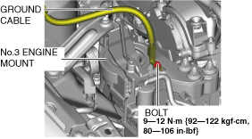
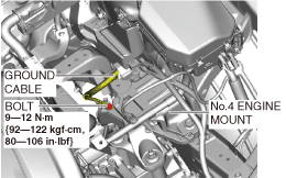
27. Remove the ground cable shown in the figure.
RH
am3zzw00034331
|
LH
am3zzw00034332
|
28. Set the cooler hose (LO) aside. (See REFRIGERANT LINE REMOVAL/INSTALLATION.)
29. Remove the A/C compressor with the cooler hose still connected and secure it using wire or rope so that it is out of the way. (See A/C COMPRESSOR REMOVAL/INSTALLATION.)
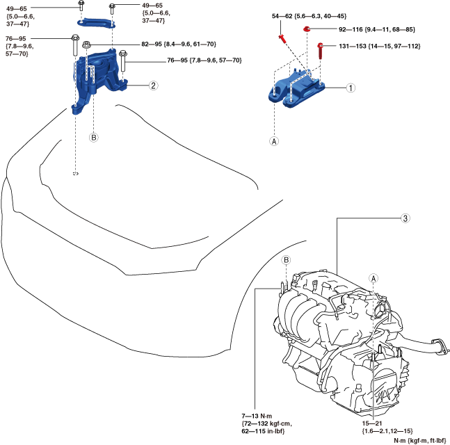
30. Remove in the order indicated in the table.
a30zzw00005580
|
|
1
|
No.4 engine mount component
|
|
2
|
No.3 engine mount
|
|
3
|
Engine, transaxle
|
Engine Installation
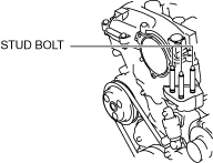
1. Tighten the engine front cover stud bolts.
am6xuw00006690
|
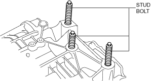
2. Tighten the transaxle stud bolts.
am6xuw00012315
|
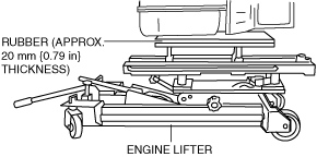
3. Secure the engine and transaxle using a commercially available engine lifter.
am3zzw00024883
|
4. Return the engine and transaxle to their original positions.
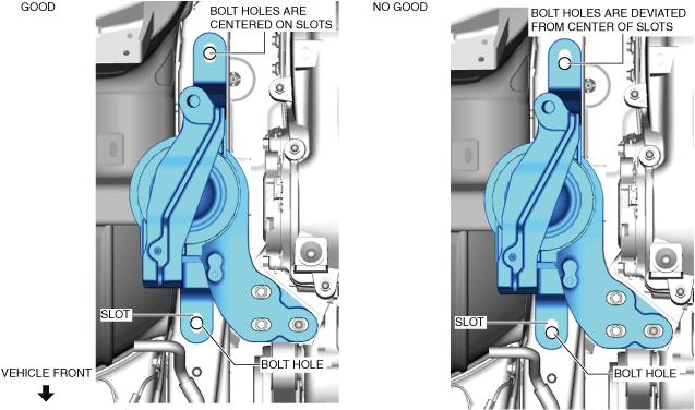
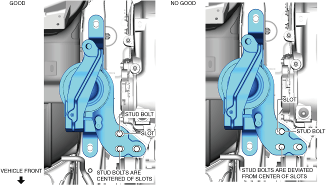
5. Temporarily tighten the No.3 engine mount installation bolts and nuts using the following procedure:
am3zzw00024884
|
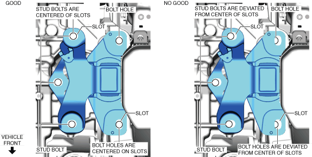
am3zzw00024885
|
6. Temporarily tighten the No.4 engine mount rubber installation bolts and nuts using the following procedure:
am3zzw00024887
|
7. Temporarily tighten the No.4 engine mount bracket installation bolts.
8. Install the transfer. (AWD) (See TRANSFER REMOVAL/INSTALLATION [ET6AX-EL].)
9. Refill the transfer oil. (AWD) (See TRANSFER OIL REPLACEMENT [ET6AX-EL].)
10. Install the exhaust manifold. (AWD) (See EXHAUST SYSTEM REMOVAL/INSTALLATION [SKYACTIV-G 2.0].)
11. Install the No.1 engine mount rubber and the front crossmember component as a single unit. (See FRONT CROSSMEMBER REMOVAL/INSTALLATION.)
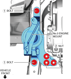
12. Tighten the No.3 engine mount installation bolts and nuts in the order shown in the figure.
am3zzw00024888
|
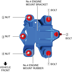
13. Tighten the No.4 engine mount bracket and rubber installation bolts and nuts in the order shown in the figure.
a30zzw00005581
|
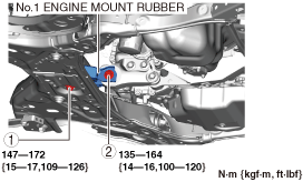
14. Tighten the No.1 engine mount rubber installation bolts.
am3zzw00034334
|
15. Install the cooler hose (LO). (See REFRIGERANT LINE REMOVAL/INSTALLATION.)
16. Connect the ground cable shown in the figure.
RH
am3zzw00034331
|
LH
am3zzw00034332
|
17. Install the A/C compressor. (See A/C COMPRESSOR REMOVAL/INSTALLATION.)
18. Install the front drive shaft. (See FRONT DRIVE SHAFT REMOVAL/INSTALLATION.)
19. Install the propeller shaft. (AWD) (See PROPELLER SHAFT REMOVAL/INSTALLATION.)
20. Install the TWC. (See EXHAUST SYSTEM REMOVAL/INSTALLATION [SKYACTIV-G 2.0].)
21. Install the generator drive belt. (See DRIVE BELT REMOVAL/INSTALLATION [SKYACTIV-G 2.0].)
22. Connect the lower radiator hose to the radiator.
23. Connect the lower radiator hose clip.
24. Install the front wheels and tires. (See WHEEL AND TIRE REMOVAL/INSTALLATION.)
25. Connect the upper radiator hose to the engine side.
26. Connect the heater hoses. (See A/C UNIT REMOVAL/INSTALLATION.)
27. Connect the fuel hose. (See QUICK RELEASE CONNECTOR (FUEL SYSTEM) REMOVAL/INSTALLATION [SKYACTIV-G 2.0].)
28. Connect the evaporative hose. (See PURGE SOLENOID VALVE REMOVAL/INSTALLATION [SKYACTIV-G 2.0].)
29. Install the battery tray and PCM component and battery. (See BATTERY REMOVAL/INSTALLATION [SKYACTIV-G 2.0].)
30. Connect the connector.
am3zzw00024881
|
31. Connect the wiring harness shown in the figure.
am3zzw00024893
|
32. Install the following parts as a single unit. (See INTAKE-AIR SYSTEM REMOVAL/INSTALLATION [SKYACTIV-G 2.0].)
33. Connect the negative battery terminal. (See NEGATIVE BATTERY TERMINAL DISCONNECTION/CONNECTION.)
34. Refill the ATF. (See AUTOMATIC TRANSAXLE FLUID (ATF) REPLACEMENT [ET6A-EL, ET6AX-EL].)
35. Refill the engine coolant. (See ENGINE COOLANT REPLACEMENT [SKYACTIV-G 2.0].)
36. Start the engine, and inspect and adjust the following:
37. Install the front splash shield. (See SPLASH SHIELD REMOVAL/INSTALLATION.)
38. Install the front under cover No.1 and No.2. (See FRONT UNDER COVER No.1 REMOVAL/INSTALLATION.) (See FRONT UNDER COVER No.2 REMOVAL/INSTALLATION.)
39. Install the plug hole plate. (See PLUG HOLE PLATE REMOVAL/INSTALLATION [SKYACTIV-G 2.0].)
CKP Sensor Learning Value Clearing Procedure
1. Shift the selector lever to the P position.
2. Perform the following procedure within 10 s.
3. Verify that the wrench indicator light turns on for approx. 3 s and turns off.