|
amxzzw00003010
ENGINE REMOVAL/INSTALLATION [SKYACTIV-G 1.5, SKYACTIV-G 2.0]
id0110h8800400
1. Disconnect the negative battery terminal. (See NEGATIVE BATTERY TERMINAL DISCONNECTION/CONNECTION.)
2. Remove the front wheels and tires. (See GENERAL PROCEDURES (SUSPENSION).)
3. Remove the front mudguard No.1 and No.2. (See FRONT MUDGUARD REMOVAL/INSTALLATION.)
4. Remove the front splash shield No.1 and No.2. (See FRONT SPLASH SHIELD No.1 REMOVAL/INSTALLATION.) (See FRONT SPLASH SHIELD No.2 REMOVAL/INSTALLATION.)
5. Disconnect the service plug. (With i-ELOOP) (See SERVICE PLUG DISCONNECTION/CONNECTION [i-ELOOP].)
6. Remove the front under cover. (See FRONT UNDER COVER REMOVAL/INSTALLATION.)
7. Remove the plate. (With plate) (See PLATE REMOVAL/INSTALLATION.)
8. Remove the front crossmember under cover. (See FRONT CROSSMEMBER UNDER COVER REMOVAL/INSTALLATION.)
9. Drain the engine coolant. (See ENGINE COOLANT REPLACEMENT [SKYACTIV-G 1.5, SKYACTIV-G 2.0].)
10. Drain the ATF. (AT) (See AUTOMATIC TRANSMISSION FLUID (ATF) REPLACEMENT [SJ6A-EL].)
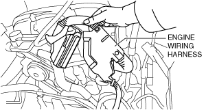
11. Disconnect the connectors shown in the figure and set the wiring harness aside.
amxzzw00003010
|
12. Remove the battery and battery tray. (See BATTERY REMOVAL/INSTALLATION [SKYACTIV-G 1.5, SKYACTIV-G 2.0].)
13. Remove the following intake air system related parts as a single unit. (With resonance chamber No.2) (See INTAKE-AIR SYSTEM REMOVAL/INSTALLATION [SKYACTIV-G 1.5, SKYACTIV-G 2.0].)
14. Remove the air cleaner, air hose and resonance chamber No.1 as a single unit. (See INTAKE-AIR SYSTEM REMOVAL/INSTALLATION [SKYACTIV-G 1.5, SKYACTIV-G 2.0].)
15. Disconnect the upper radiator hose, heater hose and secure the upper radiator hose, heater hose using wire or rope so that it is out of the way.
amxuuw00004528
|
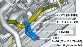
16. Remove the bolt shown in the figure and set the cooler pipe, heater hose and bracket aside.
amxzzw00004419
|
17. Disconnect the heater hose from the water outlet component side.
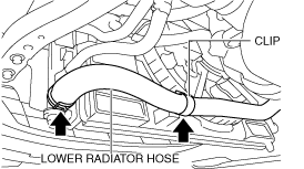
18. Disconnect the lower radiator hose from the thermostat side. (See THERMOSTAT REMOVAL/INSTALLATION [SKYACTIV-G 1.5, SKYACTIV-G 2.0].)
19. Remove the generator drive belt. (See DRIVE BELT REMOVAL/INSTALLATION [SKYACTIV-G 1.5, SKYACTIV-G 2.0].)
20. Remove the PCM and PCM bracket component. (See PCM REMOVAL/INSTALLATION [SKYACTIV-G 1.5, SKYACTIV-G 2.0].)
21. Set aside the engine wiring harness on the engine.
amxuuw00004530
|
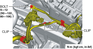
22. Remove the bolt and clips shown in the figure and set the wiring harness aside.
amxzzw00004420
|
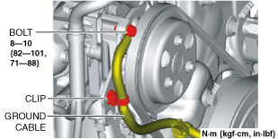
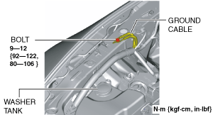
23. Disconnect the ground cable shown in the figure.
amxzzw00004421
|
24. Disconnect the vacuum hose. (See VACUUM HOSE REMOVAL/INSTALLATION [L.H.D.].) (See VACUUM HOSE REMOVAL/INSTALLATION [R.H.D.].)
25. Disconnect the evaporative hose. (See PURGE SOLENOID VALVE REMOVAL/INSTALLATION [SKYACTIV-G 1.5, SKYACTIV-G 2.0].)
26. Disconnect the fuel hose from the engine side. (See QUICK RELEASE CONNECTOR REMOVAL/INSTALLATION [SKYACTIV-G 1.5, SKYACTIV-G 2.0].)
27. Disconnect the selector lever. (AT) (See AUTOMATIC TRANSMISSION REMOVAL/INSTALLATION [SJ6A-EL].)
28. Remove the shift lever. (MT) (See TRANSMISSION REMOVAL/INSTALLATION [M66M-D].)
29. Remove the clutch release cylinder with the pipe still connected. (MT) (See CLUTCH RELEASE CYLINDER REMOVAL/INSTALLATION.)
30. Disconnect the engine wiring harness from the capacitor. (With i-ELOOP) (See CAPACITOR (i-ELOOP) REMOVAL/INSTALLATION [i-ELOOP].)
31. Disconnect the oil hoses from the radiator using the following procedure: (AT)
32. Remove in the order indicated in the table.
33. Install in the reverse order of removal.
34. Refill the ATF. (AT) (See AUTOMATIC TRANSMISSION FLUID (ATF) REPLACEMENT [SJ6A-EL].)
35. Refill the engine coolant. (See ENGINE COOLANT REPLACEMENT [SKYACTIV-G 1.5, SKYACTIV-G 2.0].)
36. Start the engine, and inspect and adjust the following:
amxzzw00005776
|
|
1
|
Center under cover (With center under cover)
|
|
2
|
Member bracket (MT)
|
|
3
|
Tunnel member
|
|
4
|
TWC
(See TWC Installation Note.)
|
|
5
|
Front crossmember component
|
|
6
|
Propeller shaft
|
|
7
|
Power plant frame
|
|
8
|
Engine, transmission
|
Front Crossmember Component Removal/Installation Note
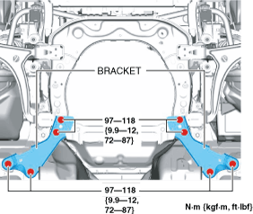
1. Remove the bracket.
amxuuw00004535
|
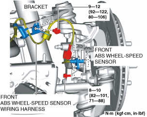
2. Remove the front ABS wheel speed sensor from the wheel hub component.
amxuuw00004536
|
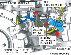
3. Remove the front ABS wheel speed sensor wiring harness from the bracket and front upper arm and set it aside so that it does not interfere with the servicing.
4. Remove the front brake hose from the front upper arm and front crossmember and set it aside so that it does not interfere with the servicing.
amxuuw00004537
|
5. Remove the front brake caliper component and secure the front brake caliper component using wire or rope so that it is out of the way. (See FRONT BRAKE DISC REMOVAL/INSTALLATION [WITH 4-POT OPPOSED PISTON CALIPER].) (See FRONT BRAKE DISC REMOVAL/INSTALLATION [WITH SINGLE PISTON FLOATING CALIPER].)
6. Remove the front disc plate. (See FRONT BRAKE DISC REMOVAL/INSTALLATION [WITH 4-POT OPPOSED PISTON CALIPER].) (See FRONT BRAKE DISC REMOVAL/INSTALLATION [WITH SINGLE PISTON FLOATING CALIPER].)
7. Remove the seal plate. (See SEAL PLATE REMOVAL/INSTALLATION.)
8. Remove the horn LO component. (See HORN REMOVAL/INSTALLATION.)
9. Remove the bumper stiffener lower. (See BUMPER STIFFENER LOWER REMOVAL/INSTALLATION.)
10. Remove the front crossmember extension. (See FRONT STABILIZER REMOVAL/INSTALLATION.)
11. Remove the oil pipe No.3 bracket from the front crossmember. (AT) (See OIL COOLER REMOVAL/INSTALLATION [SJ6A-EL].)
12. Remove the coolant reserve tank. (See COOLANT RESERVE TANK REMOVAL/INSTALLATION [SKYACTIV-G 1.5, SKYACTIV-G 2.0].)
13. Remove the upper mount rubber bracket (LH). (See RADIATOR REMOVAL/INSTALLATION [SKYACTIV-G 1.5, SKYACTIV-G 2.0].)
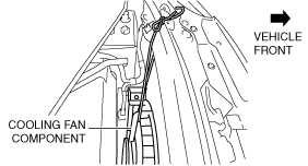
14. Suspend the cooling fan component with rope through the upper mount rubber bracket (LH) hole as shown in the figure.
amxuuw00004538
|
15. Remove the center mount rubber bracket and lower mount rubber bracket of the radiator. (See RADIATOR REMOVAL/INSTALLATION [SKYACTIV-G 1.5, SKYACTIV-G 2.0].)
16. Disconnect the intermediate shaft from the steering gear and linkage. (See INTERMEDIATE SHAFT REMOVAL/INSTALLATION.)
17. Disconnect the EPS connector. (See STEERING GEAR AND LINKAGE REMOVAL/INSTALLATION.)
18. Disconnect the lower radiator hose and clip.
amxuuw00004539
|
19. Install the SST to the position shown in the figure using the following bolt.
amxuuw00004540
|
20. Remove the bolt shown in the figure and set the ground cable aside.
amxuuw00004541
|
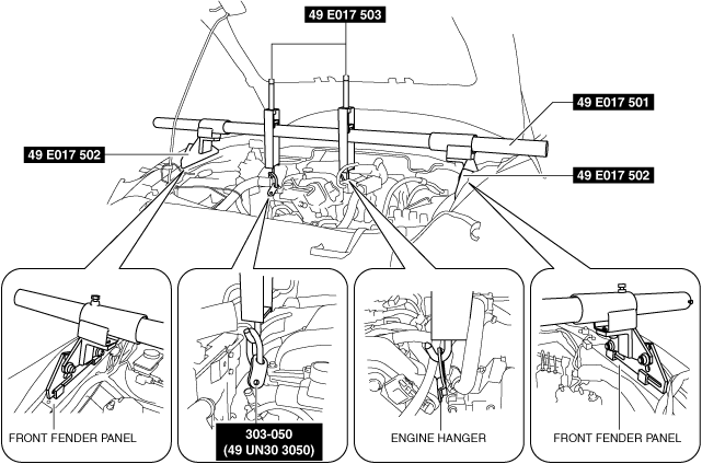
21. Set the SSTs as shown in the figure.
amxzzw00004422
|
22. Rotate the shafts of the SSTs (49 E017 503) to support the engine.
23. Remove the engine mount rubber installation bolts (front crossmember side). (See ENGINE MOUNT DISASSEMBLY/ASSEMBLY [SKYACTIV-G 1.5, SKYACTIV-G 2.0].)
24. Lift up the engine until the engine mount rubber is slightly raised above the front crossmember and verify again that the engine is securely hung.
25. Remove the front suspension tower bar. (With front suspension tower bar) (See FRONT SUSPENSION TOWER BAR REMOVAL/INSTALLATION.)
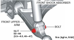
26. Remove the front shock absorber upper side nuts. (See FRONT SHOCK ABSORBER AND COIL SPRING REMOVAL/INSTALLATION.)
27. Loosen the front shock absorber lower side nuts.
amxuuw00004543
|
28. Disconnect the front stabilizer control link from the front lower arm. (See FRONT STABILIZER REMOVAL/INSTALLATION.)
29. Remove the front stabilizer bracket installation nuts and suspend the front stabilizer component. (See FRONT STABILIZER REMOVAL/INSTALLATION.)
30. Support the front crossmember component using a transmission jack.
amxuuw00004544
|
31. Remove the front crossmember installation bolts and nuts. (See FRONT STABILIZER REMOVAL/INSTALLATION.)
32. Lower the transmission jack slowly and remove the front crossmember component. (See FRONT STABILIZER REMOVAL/INSTALLATION.)
33. Install in the reverse order of removal.
Engine, Transmission Removal/Installation Note
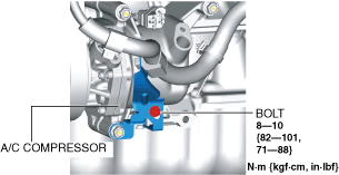
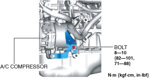
1. Remove the bolt shown in the figure.
SKYACTIV-G 1.5
amxzzw00003012
|
SKYACTIV-G 2.0
amxuuw00004545
|
2. Disconnect the A/C compressor connector.
3. Remove the A/C compressor with the cooler hose still connected and secure it using wire or rope so that it is out of the way. (See A/C COMPRESSOR REMOVAL/INSTALLATION.)
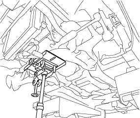
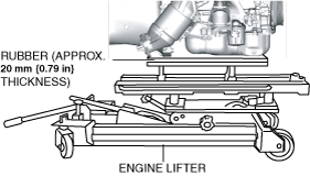
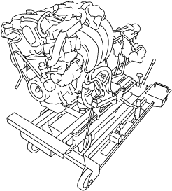
4. Secure the engine and transmission using a commercially available engine lifter.
amxzzw00003013
|
5. Remove the power plant frame. (See POWER PLANT FRAME REMOVAL [M66M-D].)
6. Remove the SST (49 E017 5A0) from the engine.
7. Lower the engine lifter and remove the engine, transmission.
amxuuw00004546
|
8. Install in the reverse order of removal.
TWC Installation Note
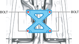
1. Temporarily remove the installed tunnel member when installing the power plant frame.
amxzzw00003628
|
2. Install the TWC. (See EXHAUST SYSTEM REMOVAL/INSTALLATION [SKYACTIV-G 1.5, SKYACTIV-G 2.0].)