AUTOMATIC TRANSAXLE ASSEMBLY
id051700664400
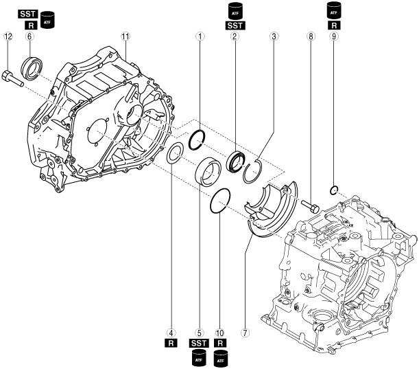
Structural View
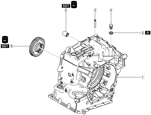
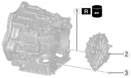
Automatic transaxle 1
|
1
|
Transaxle case
|
|
2
|
Breather pipe
|
|
3
|
Gasket
|
|
4
|
Plug (M18 x 1.5, length approx. 21.5 mm {0.846 in})
|
|
5
|
Radial needle bearing
|
|
6
|
Primary gear
|
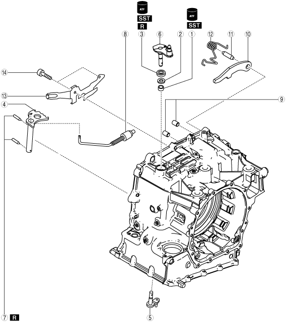
Automatic transaxle 2
|
1
|
Radial needle bearing
|
|
2
|
Washer
|
|
3
|
Oil seal
|
|
4
|
Manual plate component
|
|
5
|
Parking assist lever component
|
|
6
|
Parking shift lever component
|
|
7
|
Roll pin
|
|
8
|
Parking rod component
|
|
9
|
Parking pawl pin
|
|
10
|
Parking pawl
|
|
11
|
Parking pawl shaft
|
|
12
|
Pawl return spring
|
|
13
|
Detent bracket component
|
|
14
|
2 bolts (M6 x 1.0 bolt, length approx. 25 mm {0.98 in})
|
Automatic transaxle 3
|
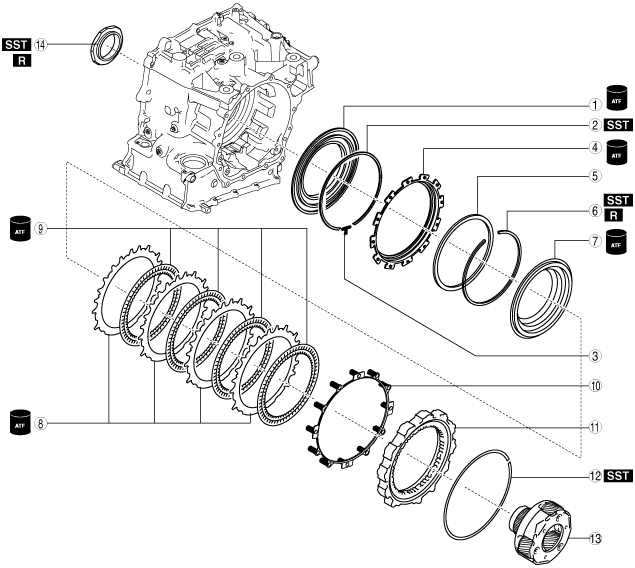
1
|
Low and reverse brake piston B1
|
|
2
|
Snap ring (outer diameter approx. 180.5 mm {7.106 in}) (selection)
|
|
3
|
Spacer
|
|
4
|
Low and reverse brake piston B2
|
|
5
|
Dished plate (outer diameter approx. 159.2 mm {6.268 in})
|
|
6
|
Snap ring (outer diameter approx. 137 mm {5.39 in})
|
|
7
|
Low and reverse brake piston A
|
|
8
|
Driven plate (inner diameter approx. 140 mm {5.51 in})
|
|
9
|
Drive plate (outer diameter approx. 162 mm {6.38 in})
|
|
10
|
Springs and retainer component (inner diameter approx. 170 mm {6.69 in})
|
|
11
|
Retaining plate
|
|
12
|
Snap ring (outer diameter approx. 191.1 mm {7.524 in}) (selection)
|
|
13
|
Front planetary gear
|
|
14
|
Locknut
|
Automatic transaxle 4
|
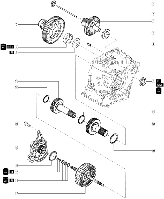
1
|
Shim (outer diameter approx. 67.4 mm {2.65 in}, thickness approx. 0.5 mm {0.02 in})
|
|
2
|
Bearing race (outer diameter approx. 68 mm {2.7 in})
|
|
3
|
Oil seal (outer diameter approx. 56 mm {2.2 in})
|
|
4
|
Plug
|
|
5
|
Thrust needle bearing (outer diameter approx. 67 mm {2.6 in})
|
|
6
|
Secondary gear and output gear
|
|
7
|
Oil pipe
|
|
8
|
Thrust needle bearing (outer diameter approx. 39.4 mm {1.55 in})
|
|
9
|
Ring gear and differential
|
|
10
|
Thrust needle bearing (outer diameter approx. 66.2 mm {2.61 in})
|
|
11
|
Seal ring (outer diameter approx. 24.6 mm {0.969 in}, thickness approx. 1.5 mm {0.059 in})
|
|
12
|
D-ring (outer diameter approx. 16.3 mm {0.642 in}, thickness approx. 1.6 mm {0.063 in})
|
|
13
|
Low clutch hub
|
|
14
|
Thrust needle bearing (outer diameter approx. 44 mm {1.7 in})
|
|
15
|
High clutch hub
|
|
16
|
Thrust needle bearing (outer diameter approx. 32.6 mm {1.28 in})
|
|
17
|
Clutch component
|
|
18
|
Thrust washer (inner diameter approx. 58.7 mm {2.31 in})
|
|
19
|
Oil pump
|
|
20
|
7 bolts (M8 x 1.25 bolt, length approx. 31 mm {1.2 in})
|
Automatic transaxle 5
|
1
|
Shim (outer diameter approx. 43 mm {1.7 in}) (selection)
|
|
2
|
Roller bearing (outer diameter approx. 62 mm {2.4 in})
|
|
3
|
Snap ring (outer diameter approx. 67 mm {2.6 in})
|
|
4
|
Shim (outer diameter approx. 67.4 mm {2.65 in}) (selection)
|
|
5
|
Bearing race (outer diameter approx. 68 mm {2.7 in})
|
|
6
|
Oil seal (outer diameter approx. 56 mm {2.2 in})
|
|
7
|
Baffle plate
|
|
8
|
3 bolts (M6 x 1.0 bolt, length approx. 14 mm {0.55 in})
|
|
9
|
O-ring (outer diameter approx. 15.6 mm {0.614 in}, thickness approx. 2.4 mm {0.094 in})
|
|
10
|
O-ring (outer diameter approx. 73.3 mm {2.89 in}, thickness approx. 3.0 mm {0.12 in})
|
|
11
|
Converter housing
|
|
12
|
21 bolts * (M8 x 1.25 bolt, length approx. 28 mm {1.1 in})
|
* :Of the 21 bolts, 4 are applied with sealant
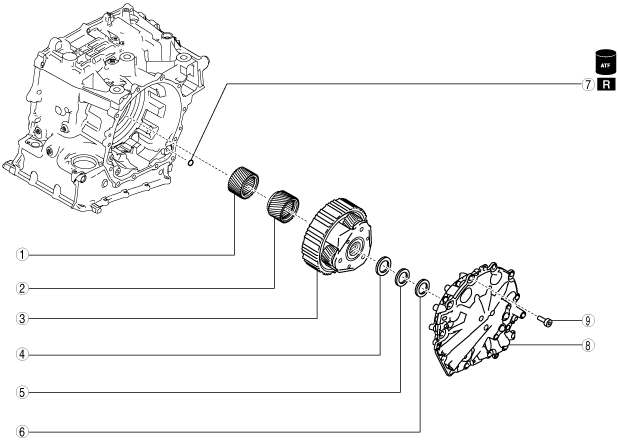
Automatic transaxle 6
|
1
|
Front sun gear
|
|
2
|
Rear sun gear
|
|
3
|
Rear planetary gear
|
|
4
|
Thrust needle bearing (outer diameter approx. 44 mm {1.7 in})
|
|
5
|
Bearing race (outer diameter approx. 41.2 mm {1.62 in})
|
|
6
|
Shim (outer diameter approx. 39.8 mm {1.57 in}) (selection)
|
|
7
|
O-ring (outer diameter approx. 15.6 mm {0.614 in}, thickness approx. 2.4 mm {0.094 in})
|
|
8
|
End cover component
|
|
9
|
12 bolts * (M8 x 1.25 bolt, length approx. 21 mm {0.83 in})
|
* :Of the 12 bolts, 3 are applied with sealant
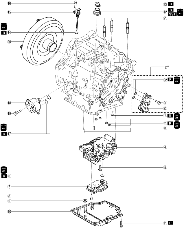
Automatic transaxle 7
|
1
|
O-ring (outer diameter approx. 15.6 mm {0.614 in}, thickness approx. 2.4 mm {0.094 in})
|
|
2
|
Gasket
|
|
3
|
Dowel pin
|
|
4
|
Control valve body
|
|
5
|
7 bolts (M6 x 1.0 bolt, length approx. 50 mm {2.0 in})
|
|
6
|
O-ring (outer diameter approx. 29.5 mm {1.16 in}, thickness approx. 3 mm {0.1 in})
|
|
7
|
Oil strainer
|
|
8
|
Bolt (M6 x 1.0 bolt, length approx. 16 mm {0.63 in})
|
|
9
|
Magnet
|
|
10
|
Oil pan
|
|
11
|
16 bolts (M6 x 1.0 bolt, length approx. 15 mm {0.59 in}1*)
|
|
12
|
Oil seal
|
|
13
|
Hose clamp
|
|
14
|
O-ring (outer diameter approx. 16.6 mm {0.654 in}, thickness approx. 2.4 mm {0.094 in})
|
|
15
|
Dipstick
|
|
16
|
Bolt (M6 x 1.0 bolt, length approx. 16 mm {0.63 in})
|
|
17
|
O-ring (outer diameter approx. 24.4 mm {0.961 in}, thickness approx. 2.4 mm {0.094 in})
|
|
18
|
Oil cooler
|
|
19
|
3 bolts (M8 x 1.25 bolt, length approx. 23.5 mm {0.925 in})
|
|
20
|
Torque converter
|
|
21
|
Stud bolt
|
|
22
|
O-ring (outer diameter approx. 15.6 mm {0.614 in}, thickness approx. 2.4 mm {0.094 in})2*
|
|
23
|
Electric AT oil pump2*
|
|
24
|
3 bolts (M8 x 1.25 bolt, length approx. 25 mm {0.98 in})2*
|
1* :Length without spring washer is indicated due to bolt with spring washer. Length with spring washer is approx. 13 mm {0.51 in}.
2* :Only vehicles with i-stop
Assembly Procedure
1. Assemble the parts in the following order.
-
Note
-
• Assemble the parts in the following order because the parts in the transaxle may be used for measurement/adjustment.
- (1) Oil pump (See OIL PUMP ASSEMBLY.)
- (2) Clutch component (See CLUTCH COMPONENT ASSEMBLY.)
- (3) Secondary gear and output gear (See SECONDARY GEAR AND OUTPUT GEAR ASSEMBLY.)
- (4) Ring gear and differential (See RING GEAR AND DIFFERENTIAL ASSEMBLY.)
- (5) End cover component (See END COVER COMPONENT ASSEMBLY.)
- (6) Control valve body (See CONTROL VALVE BODY ASSEMBLY.)
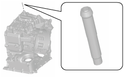
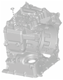
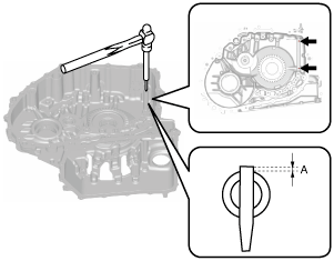
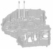
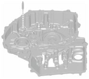
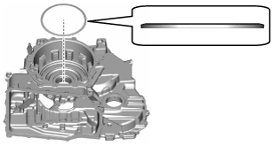
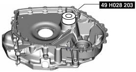
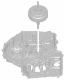
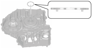
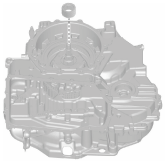
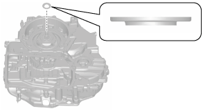
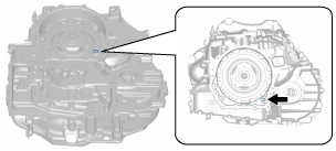
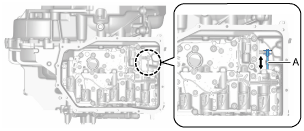
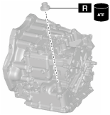
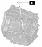
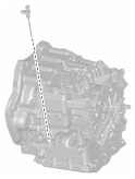
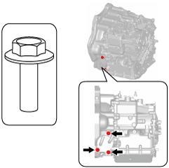
2. If the transaxle case is replaced with a new one, perform the following procedure:
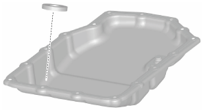
- (1) Remove the stud bolts.
-
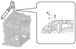
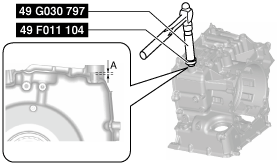
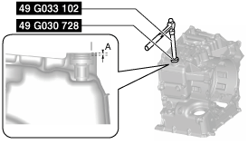
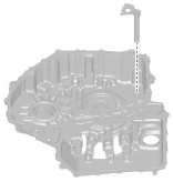
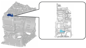
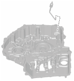
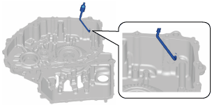
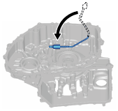
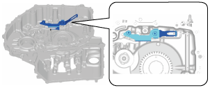
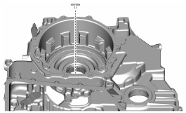
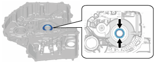
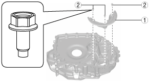
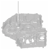
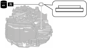
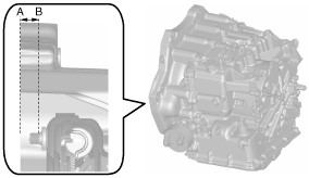
- (2) Assemble a new breather pipe to the position shown in the figure.
-
-
Note
-
• Lightly tap and assemble so as not to deform the breather pipe.
A :17—19 mm {0.67—0.74 in}
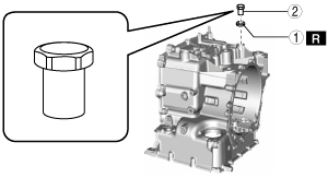
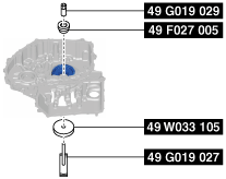
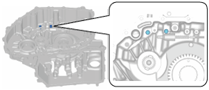
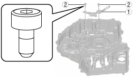
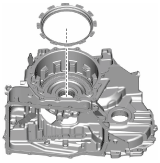
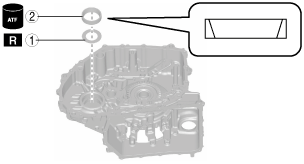
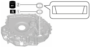
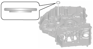
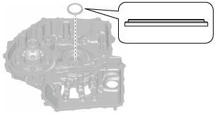
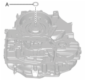
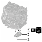
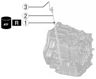
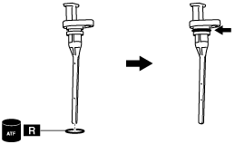
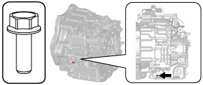
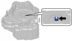
- (3) Assemble the plug and new gasket in the order shown in the figure.
-
-
Caution
-
• If a gasket is reused it could cause ATF leakage, therefore use a new gasket.
|
1
|
Gasket
|
|
2
|
Plug (M18 x 1.5, length approx. 21.5 mm {0.846 in})
|
-
Plug tightening torque
-
39—59 N·m {4.0—6.0 kgf·m, 29—43 ft·lbf}
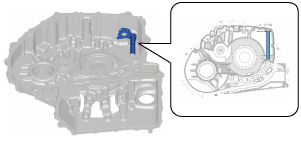
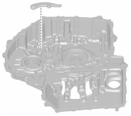
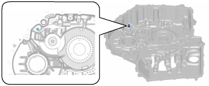
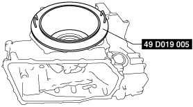
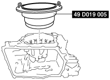
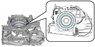
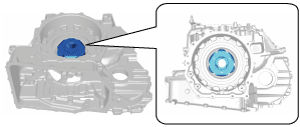
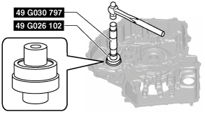
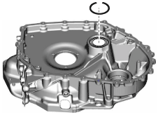
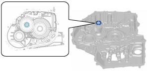
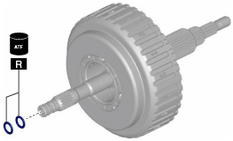
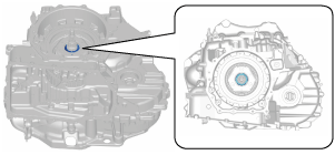
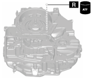
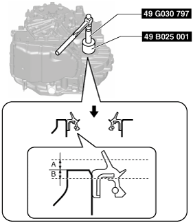
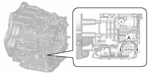
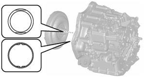
- (4) Assemble a new radial needle bearing using the following procedure:
-
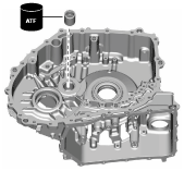
- 1) Apply ATF (ATF FZ) to the engagement area of the new radial needle bearing and transaxle case.
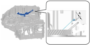
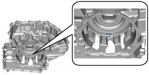
- 2) Assemble the new radial needle bearing to the position shown in the figure using the SST.
-
A :1.9—2.9 mm {0.08—0.11 in}
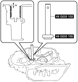
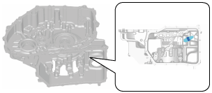
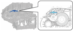
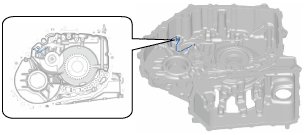
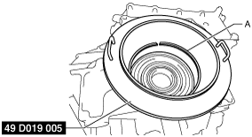
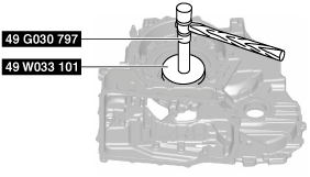
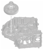
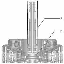
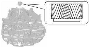
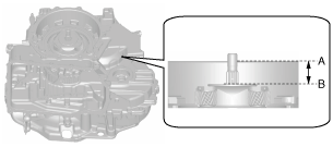
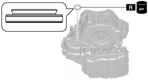
- (5) Assemble a new radial needle bearing using the following procedure:
-
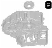
- 1) Apply ATF (ATF FZ) to the engagement area of the new radial needle bearing and transaxle case.
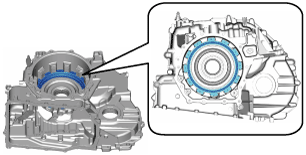
- 2) Assemble the new radial needle bearing to the position shown in the figure using the SST.
-
A :1.8—2.3 mm {0.071—0.090 in}
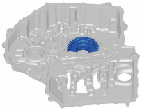
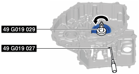
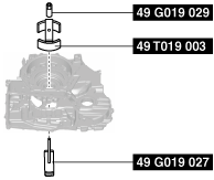
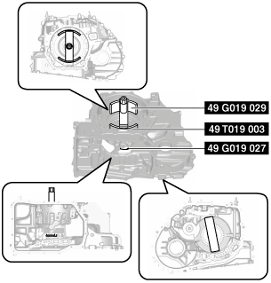
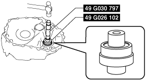
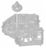
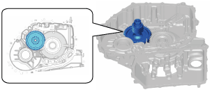
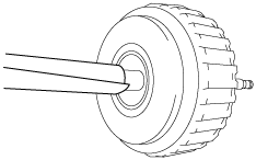
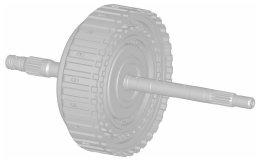
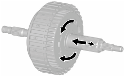
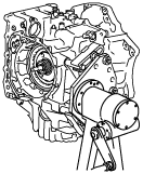
3. Assemble the primary gear using the following procedure:
-
Note
-
• Perform this procedure only if the transaxle case is replaced with a new one.
- (1) Apply ATF (ATF FZ) to the engagement area of the primary gear and angular contact ball bearing.
- (2) Assemble the primary gear on the angular contact ball bearing.
-
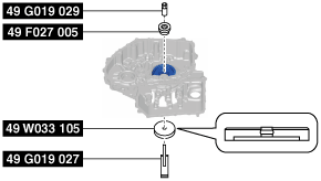
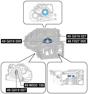
- (3) Install the SSTs.
-
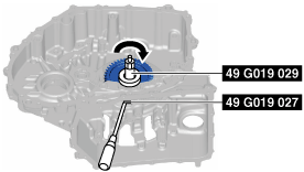
- (4) Lock the SST (49 G019 027) against rotation using a flathead screwdriver, tighten the SST (49 G019 029), and assemble the primary gear.
-
- (5) Loosen the SST (49 G019 029) and remove the SSTs.
-
-
Note
-
• Lock the SST (49 G019 027) against rotation using a flathead screwdriver and loosen the SST (49 G019 029).
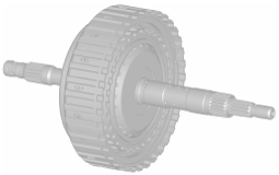
4. Assemble the washer.
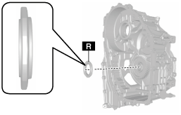
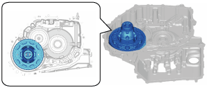
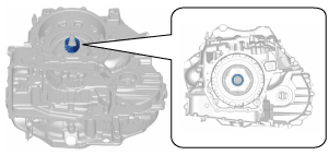
5. Assemble a new oil seal using the following procedure:
-
Caution
-
• If an oil seal is reused it could cause ATF leakage, therefore use a new oil seal.
- (1) Apply ATF (ATF FZ) to the engagement area of the new oil seal and transaxle case.
- (2) Apply ATF (ATF FZ) to the lip of the new oil seal.
- (3) Assemble the new oil seal to the position shown in the figure using the SST.
-
A :-0.3—0.3 mm {-0.01—0.01 in}
6. Assemble the manual plate component.
7. Assemble the parking assist lever component.
-
Note
-
• Pass the end of the parking assist lever component through the assembly hole of the transaxle case, and assemble it to the manual plate component.
8. Assemble the parking shift lever component.
-
Note
-
• Pass the end of the parking shift lever component through the assembly hole (radial needle bearing) of the transaxle case, and assemble it to the manual plate component.
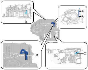
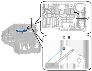
9. Assemble new roll pins using the following procedure:
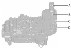
- (1) Set the manual plate component, parking assist lever component, and the parking shift lever component as shown in the figure and align with the roll pin holes.
-
A :Roll pin hole
B :Manual plate component
C :Parking assist lever component
D :Parking shift lever component
- (2) Assemble new roll pins to the positions shown in the figure using a pin punch.
-
-
Note
-
• Use a pin punch with an end outer diameter of 5 mm {0.2 in} or more.
A :0—1 mm {0—0.03 in}
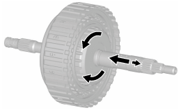
10. Assemble the parking rod component using the following procedure:
- (1) Align the parking rod component projection to the key hole of the manual plate component and assemble.
-
- (2) Rotate the parking rod component as shown in the figure.
-
11. Assemble the parking pawl pin.
12. Assemble the parking pawl.
13. Assemble the parking pawl shaft.
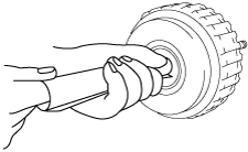
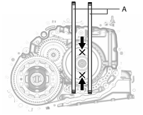
14. Assemble the pawl return springs using the following procedure:
- (1) Assemble the pawl return springs.
-
- (2) To verify that the parts are securely assembled, move the parking pawl in the direction of (1) using a screwdriver, and verify that the parking pawl returns to its original position (direction (2)) when removing your hand.
-
A :Parking pawl
-
• If there is a malfunction, remove the pawl return springs and reassemble.
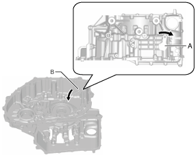
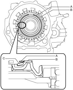
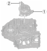
15. Assemble the detent bracket component using the following procedure:
- (1) Rotate the parking shift lever component (manual plate component) as shown in the figure.
-
A :Parking shift lever component
B :Manual plate component
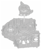
- (2) Assemble the detent bracket component using the procedure shown in the figure.
-
-
Caution
-
• When tightening bolts, verify that the detent bracket component does not interfere with the manual plate component to prevent damaging the part.
|
1
|
Detent bracket component
|
|
2
|
Bolt (M6 x 1.0 bolt, length approx. 25 mm {0.98 in})
|
A :Gap
-
Detent bracket component assembly bolt tightening torque
-
8—11 N·m {82—112 kgf·cm, 71—97 in·lbf}
- (3) Rotate the parking shift lever component (manual plate component) as shown in the figure, and align the detent bracket component with the groove of the manual plate component.
-
A :Parking shift lever component
B :Manual plate component
C :Detent bracket component
16. Assemble low and reverse brake piston B1 using the following procedure:
- (1) Apply ATF (ATF FZ) to the lip of low and reverse brake piston B1.
- (2) Assemble low and reverse brake piston B1.
-
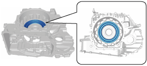
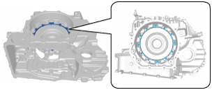
17. Assemble the snap ring using the following procedure:
-
Note
-
• Snap ring size: Outer diameter approx. 180.5 mm {7.106 in}
- (1) Measure the low and reverse brake (piston B1) clearance and select the appropriate snap ring. (See LOW AND REVERSE BRAKE (PISTON B1) CLEARANCE MEASUREMENT/ADJUSTMENT.)
-
-
Note
-
• If the snap ring is assembled for the low and reverse brake (piston B1) clearance measurement/adjustment, the following snap ring assembly procedure is not necessary.
- (2) Install the SSTs.
-
- (3) Install the snap ring selected in Step (1) to the SST.
-
A :Snap ring (selection)
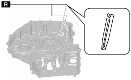
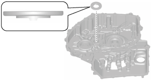
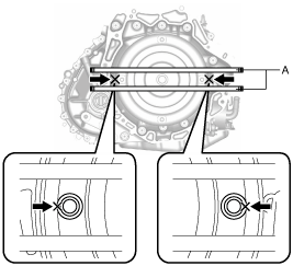
- (4) Rotate the SST and adjust the snap ring so that the end gap of the snap ring is in the oil passage area shown in the figure.
-
- (5) Assemble the snap ring.
- (6) Remove the SSTs.
-
-
Note
-
• Remove the SST in the lateral direction because the gap between the SST and the part is small.
- (7) Verify that the end gap of the snap ring is assembled to the position shown in the figure.
-
18. Assemble the spacer.
19. Assemble low and reverse brake piston B2 using the following procedure:
- (1) Apply ATF (ATF FZ) to the lip of low and reverse brake piston B2.
- (2) Assemble low and reverse brake piston B2.
-
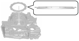
20. Assemble the dished plate.
-
Note
-
• Dished plate size: Outer diameter approx. 159.2 mm {6.268 in}
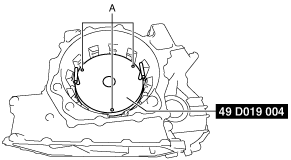
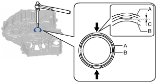
21. Assemble the snap ring using the following procedure:
-
Note
-
• Snap ring size: Outer diameter approx. 137 mm {5.39 in}
- (1) Temporarily assemble the snap ring to the outer circumference of edge part of low and reverse brake piston B1.
-
A :Snap ring
B :Low and reverse brake piston B1
C :Dished plate
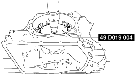
- (2) Install the SST as shown in the figure.
-
-
Caution
-
• To prevent the dished plate contact surface of the SST (49 D019 004) from deforming, avoid significant impact to the SST (49 D019 004) when assembling the automatic transmission.
A :Holes
- (3) Rotate the SST so that the end gap of the snap ring and the holes of the SST are not in the same positions.
- (4) Set the SST and part to the press as shown in the figure and press with 30000 N {3059.2 kgf, 6744.3 lbf}.
-
- (5) Insert a small flathead screwdriver into the holes (three locations) of the SST and assemble the snap ring.
-
A :Such as small flathead screwdriver
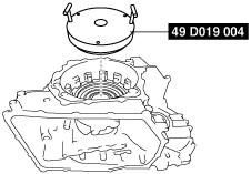
- (6) Take the SST and part off the press.
- (7) Remove the SST.
-
-
Caution
-
• To prevent the dished plate contact surface of the SST (49 D019 004) from deforming, avoid significant impact to the SST (49 D019 004) when assembling the automatic transmission.
- (8) Verify that the snap ring is securely assembled.
-
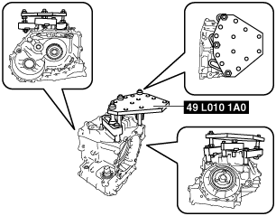
22. Install the transaxle case to the SST (engine stand) using the following procedure:
- (1) Install the SST to the transaxle case using the following procedure.
-
-
Note
-
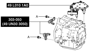
• When installing the SST (49 L010 1A0) to the transaxle case (stud bolt holes), use new part number: 9YA02 1440 or M14 x 1.5 bolts, length 100 mm {3.94 in}.
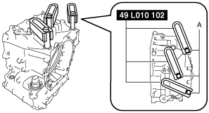
- 1) Temporarily install the arms (49 L010 102) using new part number: 9YA02 1440, or M14 x 1.5 bolts, length 100 mm {3.94 in}.
-
-
Note
-
• To adjust the installation position of the SST in Step 3), temporarily tighten the bolts.
A :Part number: 9YA02 1440, or M14 x 1.5 bolt, length 100 mm {3.94 in}
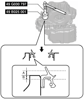
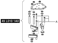
- 2) Assemble the SST (49 L010 1A0).
-
-
Note
-
• Use bolts (49 L010 105) with a length of 138 mm {5.43 in}.
A :Washer
B :Approx. 20 mm {0.79 in}
C :Approx. 18 mm {0.71 in}
D :Approx. 47 mm {1.9 in}
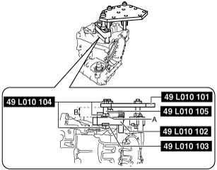
- 3) Install the SST assembled in Step 2).
-
-
Note
-
• Adjust so that the plate (49 L010 101) and arms (49 L010 102) are level, and install.
A :Washer
B :Level out
- 4) Verify that nothing other than the SST arms (49 L010 102) installation area contacts the transaxle case and breather pipe.
-
-
Caution
-
• If something other than the SST arms (49 L010 102) installation area contacts the transaxle case and breather pipe, readjust the SST to prevent damaging the part.
- 5) Tighten the nuts and bolts.
-
-
Tightening torque
-
• Bolt: Part number: 9YA02 1440, or M14 x 1.5 bolt, length 100 mm {3.94 in}
39.2—52.0 N·m {4.1—5.3 kgf·m, 30—38 ft·lbf}
• Nut: 49 L010 104
140—160 N·m {15—16 kgf·m, 104—118 ft·lbf}
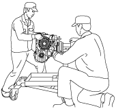
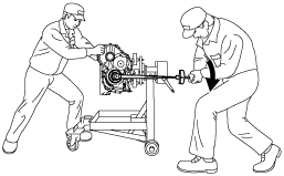
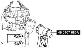
- (2) Install the transaxle case to the SST (engine stand) using part number: 9YA02 A220, or M12 x 1.75 bolt, length 40 mm {1.6 in}.
-
-
Caution
-
• For safety purposes, perform the procedure using two people, one installs the transaxle case to the SST and the other supports the transaxle case.
-
Note
-
• Tighten the four locations with bolts and securely install the transaxle case to the SST (engine stand).
A :Part number: 9YA02 A220, or M12 x 1.75 bolt, length 40 mm {1.6 in}
-
Tightening torque
-
88—118 N·m {9.0—12 kgf·m, 65—87 ft·lbf}
23. Assemble low and reverse brake piston A using the following procedure:
- (1) Apply ATF (ATF FZ) to the lip of low and reverse brake piston A.
- (2) Assemble low and reverse brake piston A.
-
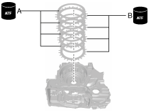
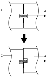
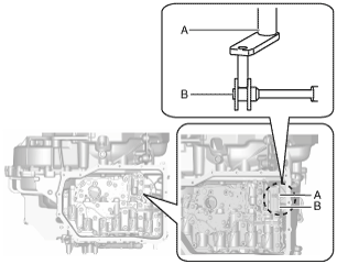
24. Assemble the drive plates and driven plates using the following procedure:
-
Note
-
• Drive plate size: Outer diameter approx. 162 mm {6.38 in}
• Driven plate size: Inner diameter approx. 140 mm {5.51 in}
- (1) Apply ATF (ATF FZ) to the drive plates and driven plates.
-
-
Caution
-
• If the drive plate is replaced with a new one, immerse it in ATF (ATF FZ) for 2 h or more to permeate the facing with ATF.
- (2) Assemble the drive plates and driven plates.
-
-
Assembly order
-
Driven plate—drive plate—driven plate—drive plate—driven plate—drive plate—driven plate—drive plate
A :Drive plate
B :Driven plate
25. Measure the low and reverse brake (piston A) clearance and select the appropriate snap ring. (See LOW AND REVERSE BRAKE (PISTON A) CLEARANCE MEASUREMENT/ADJUSTMENT.)
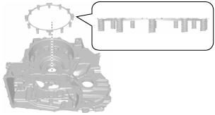
26. Assemble the springs and retainer component.
-
Note
-
• Springs and retainer component size: Inner diameter approx. 170 mm {6.69 in}
27. Assemble the retaining plate.
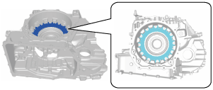
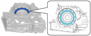
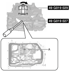
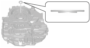
28. Assemble the snap ring using the following procedure:
-
Note
-
• Snap ring size: Outer diameter approx. 191.1 mm {7.524 in}
- (1) Install the SSTs.
-
- (2) Tighten the SST (49 G019 029) until the snap ring groove of the transaxle case comes out.
-
-
Caution
-
• If the SST (49 G019 029) is tightened with excessive force, surrounding parts could be damaged. Stop tightening the SST when the snap ring groove of the transaxle case comes out.
-
Note
-
• Lock the SST (49 G019 027) against rotation using a flathead screwdriver and tighten the SST (49 G019 029).
A :Snap ring groove
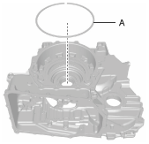
- (3) Assemble the snap ring selected in Step 25 to the position shown in the figure.
-
-
Caution
-
• After assembling the snap ring, verify that the snap ring is securely inserted into the bottom of the snap ring groove.
A :Selection
- (4) Loosen the SST (49 G019 029) and remove the SSTs.
-
-
Note
-
• Lock the SST (49 G019 027) against rotation using a flathead screwdriver and loosen the SST (49 G019 029).
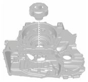
29. Assemble the front planetary gear.
30. Assemble a new locknut using the following procedure:
-
Caution
-
• Because the front planetary gear will drop if the end cover side is pointed downward before assembling the locknut, rotate the engine stand rotation handle, adjust so that the end cover side is situated sideways, and assemble the locknut.
• Always use a new locknut. If the removed locknut is reused, it may cause a transaxle malfunction.
• For tightening the locknut, 130—150 N·m {14—15 kgf·m, 96—110 ft·lbf} torque is required. For safety purposes, perform the procedure using two people, one tightens the locknut and the other supports the engine stand (transaxle case).
- (1) Rotate and adjust the rotation handle of the engine stand so that the end cover side is situated sideways.
-
- (2) Assemble and temporarily tighten a new locknut.
-
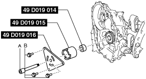
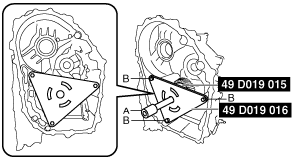
- (3) Install the SSTs.
-
-
Note
-
• Engage the three projections of the SST (49 D019 015) with the three holes of the primary gear.
• When installing the SST (49 D019 016), use the bolts supplied with the SST (49 D019 016), or M8 × 1.25 bolt (length 18 mm {0.71 in}).
A :Extension bar
B :Bolt supplied with SST (49 D019 016) or M8 x 1.25 (length 18 mm {0.71 in})
A :Extension bar
B :Bolt supplied with SST (49 D019 016) or M8 x 1.25 (length 18 mm {0.71 in})
-
SST installation bolt tightening torque
-
19—25 N·m {2.0—2.5 kgf·m, 15—18 ft·lbf}
- (4) Tighten the locknut.
-
-
Caution
-
• For tightening the locknut, 130—150 N·m {14—15 kgf·m, 96—110 ft·lbf} torque is required. For safety purposes, perform the procedure using two people, one tightens the locknut and the other supports the engine stand (transaxle case).
-
Tightening torque
-
130—150 N·m {14—15 kgf·m, 96—110 ft·lbf}
- (5) Remove the SSTs.
-
A :Extension bar
B :Bolt supplied with SST (49 D019 016) or M8 x 1.25 (length 18 mm {0.71 in})
- (6) Crimp the locknut at the two positions shown in the figure using a pin punch.
-
A :Locknut flange
B :Front planetary gear end
C :0—0.1 mm {0—0.003 in}
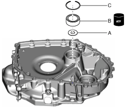
31. Assemble the bearing race and a new shim using the following procedure:
-
Caution
-
• Always use a new shim. If a deformed shim is reused, it may cause a transaxle malfunction.
- (1) Apply ATF (ATF FZ) to the engagement area of the bearing race and transaxle case.
- (2) Using the SST, assemble the bearing race and a new shim using the following procedure:
-
|
1
|
Shim (outer diameter approx. 67.4 mm {2.65 in}, thickness approx. 0.5 mm {0.02 in})
|
|
2
|
Bearing race (outer diameter approx. 68 mm {2.7 in})
|
32. Press the angular contact ball bearing to the primary gear side using the following procedure:
-
Caution
-
• To reduce error during the total end play measurement, accurately perform the following procedure:
-
Note
-
• Work overview
-
― There is a gap between the snap ring groove of the angular contact ball bearing, snap ring, and the snap ring groove of the transaxle case because the angular contact ball bearing is fixed to the transaxle case by the snap ring.
The gap causes an error during the total end play measurement.
Using the following procedure, the error during the total end play measurement is reduced by moving the angular contact ball bearing to the standard position.
A :Transaxle case
B :Snap ring
C :Angular contact ball bearing
- (1) Press the angular contact ball bearing to the primary gear side using the SSTs.
-
-
Caution
-
• Do not strongly tap the SST contacting the front planetary gear to prevent damage to the parts.
-
Note
-
• Lightly tap the SST contacting the front planetary gear 2-3 times using a plastic hammer and press the angular contact ball bearing to the primary gear side.
33. Assemble the accessories included in the converter housing using the following procedure:
- (1) Assemble the shim, roller bearing, and snap ring using the following procedure:
-
- 1) Measure the secondary gear and output gear end play and select the appropriate shim. (See SECONDARY GEAR AND OUTPUT GEAR END PLAY MEASUREMENT/ADJUSTMENT.)
- 2) Assemble the shim selected in Step (1).
-
-
Note
-
• Shim size: Outer diameter approx. 43 mm {1.7 in}
A :Shim (selection)
B :Roller bearing
C :Snap ring
- 3) Apply ATF (ATF FZ) to the engagement area of the roller bearing and converter housing.
- 4) Assemble the roller bearing using the SST.
-
-
Note
-
• Roller bearing size: Outer diameter approx. 62 mm {2.4 in}
- 5) Assemble the snap ring.
-
-
Note
-
• Snap ring size: Outer diameter approx. 67 mm {2.6 in}
- (2) Assemble the bearing race and a new shim using the following procedure:
-
-
Caution
-
• Always use a new shim. If a deformed shim is reused, it may cause a transaxle malfunction.
- 1) Measure the ring gear and differential preload and select the appropriate new shim. (See RING GEAR AND DIFFERENTIAL PRELOAD MEASUREMENT/ADJUSTMENT.)
-
-
Note
-
• If the bearing race and a new shim are assembled for the ring gear and differential preload measurement/adjustment, the following assembly procedure for the bearing race and a new shim is not necessary.
- 2) Apply ATF (ATF FZ) to the engagement area of the bearing race and converter housing.
- 3) Using the SST, assemble the bearing race and the new shim selected in Step 1) using the following procedure:
-
|
1
|
Shim (outer diameter approx. 67.4 mm {2.65 in}) (selection)
|
|
2
|
Bearing race (outer diameter approx. 68 mm {2.7 in})
|
- (3) Assemble the baffle plate using the procedure shown in the figure.
-
|
1
|
Baffle plate
|
|
2
|
Bolt (M6 x 1.0 bolt, length approx. 14 mm {0.55 in})
|
-
Baffle plate assembly bolt tightening torque
-
7.8—10.8 N·m {82—101 kgf·cm, 71—88 in·lbf}
34. Assemble the plug.
35. Assemble the thrust needle bearing.
-
Note
-
• Thrust needle bearing size: Outer diameter approx. 67 mm {2.6 in}
36. Assemble the secondary gear and output gear.
37. Assemble the oil pipe.
-
Caution
-
• Do not assemble the oil pipe using a tool such as a hammer so as to prevent damaging the new part. For the oil pipe assembly, it is better to only use your hands to put the oil pipe into the output gear.
38. Assemble the thrust needle bearing.
-
Note
-
• Thrust needle bearing size: Outer diameter approx. 39.4 mm {1.55 in}
39. Assemble the ring gear and differential.
40. Assemble the thrust needle bearing.
-
Note
-
• Thrust needle bearing size: Outer diameter approx. 66.2 mm {2.61 in}
41. Assemble new seal rings to the clutch component using the following procedure:
-
Caution
-
• If a seal ring is reused it could cause ATF leakage, therefore use a new seal ring.
|
1
|
Seal ring (end cover side) (outer diameter approx. 24.6 mm {0.969 in}, thickness approx. 1.5 mm {0.059 in})
|
|
2
|
Seal ring (center section) (outer diameter approx. 24.6 mm {0.969 in}, thickness approx. 1.5 mm {0.059 in})
|
|
3
|
Seal ring (torque converter side) (outer diameter approx. 24.6 mm {0.969 in}, thickness approx. 1.5 mm {0.059 in})
|
- (1) Apply ATF (ATF FZ) to the new seal rings.
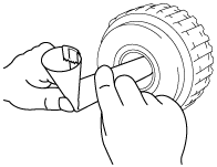
- (2) Roll an A4-size piece of paper onto the maximum diameter of the shaft.
-
-
Note
-
• Rolled piece of paper inner diameter approx. 27 mm {1.1 in}
- (3) Secure both ends of the rolled piece of paper with tape as shown in the figure.
-
A :Tape
- (4) Align the rolled piece of paper with the seal ring groove of the clutch component.
-
-
Note
-
• The figure shows the seal ring groove (end cover side) lined up.
A :Rolled piece of paper
B :Seal ring (end cover side) installation position
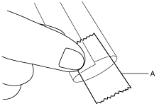
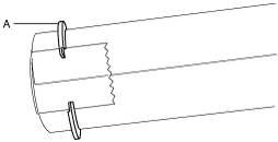
- (5) Bend the rolled piece of paper to the end of the shaft.
-
- (6) Attach the new seal ring to the position approx. 5 mm {0.2 in} from the insertion side of the end of the rolled piece of paper, and align the seal ring end gap to the position of the tape.
-
-
Caution
-
• Be careful not to open the seal ring too much, it might become damaged.
A :Seal ring
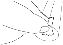
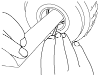
- (7) Assemble the seal ring in the groove by pushing the seal ring evenly with a precision driver (Phillips).
-
-
Caution
-
• Because an operation malfunction might occur, verify that the seal ring is assembled to the groove.
- (8) Assemble the seal ring (center section) using the same procedure from Steps 1 to 7.
- (9) Assemble the seal ring (torque converter side) to the groove while using a finger to widen the seal ring.
-
-
Caution
-
• Be careful not to open the seal ring too much, it might become damaged.
42. Assemble new D-rings to the clutch component using the following procedure:
-
Caution
-
• If a D-ring is reused it could cause ATF leakage, therefore use a new D-ring.
- (1) Apply ATF (ATF FZ) to the new D-rings.
- (2) Assemble the new D-rings to the clutch component.
-
-
Note
-
• D-ring size: Outer diameter approx. 16.3 mm {0.642 in}, thickness approx. 1.6 mm {0.063 in}
43. Assemble together the clutch component, high clutch hub, low clutch hub, and thrust needle bearing using the following procedure:
- (1) Assemble the parts using the procedure shown in the figure:
-
|
1
|
Clutch component
|
|
2
|
Thrust needle bearing (outer diameter approx. 32.6 mm {1.28 in})
|
|
3
|
High clutch hub
|
|
4
|
Thrust needle bearing (outer diameter approx. 44 mm {1.7 in})
|
|
5
|
Low clutch hub
|
-
Note
-
• For the high clutch hub and low clutch hub assembly, assembly is easier if the work is performed using the following procedure:
-
― High clutch hub
-
1. Place the assembled parts on the workbench with the clutch component situated sideways.
2. While rotating the high clutch hub, engage the splines of each of the high clutch drive plates one by one, and assemble.
― Low clutch hub
-
1. Place the assembled parts on the workbench with the clutch component situated sideways.
2. While rotating the low clutch hub, engage the splines of each of the low clutch drive plates one by one, and assemble.
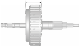
- (2) To verify that the parts are securely assembled together, measure the distance shown in the figure.
-
-
Note
-
• Recommended measuring instrument: Vernier caliper
-
Specification
-
60.60—62.09 mm {2.386—2.444 in}
-
• If not within the specification, disassemble the assembled parts and reassemble.
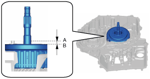
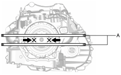
44. Assemble the parts which were assembled together in Step 43 using the following procedure:
- (1) Assemble the parts assembled together in Step 43.
-
- (2) To verify that the parts are securely assembled, measure the distance shown in the figure.
-
-
Note
-
• Recommended measuring instrument: Depth gauge, straight edge ruler
A :Transaxle case end (alignment surface with converter housing)
B :Clutch component end
-
Specification
-
8.46—9.88 mm {0.334—0.388 in}
-
• If not within the specification, remove the parts and perform re-assembly from Step 43.
-
Note
-
- 1) Set two straight edge rulers along the alignment surface of the transaxle case with the converter housing as shown in the figure.
- 2) Measure the positions (2 locations) shown in the figure using a depth gauge and calculate the average value.
-
A :Straight edge ruler
- 3) Subtract the thickness of the straight edge ruler from the average value.
45. Assemble the thrust washer.
-
Note
-
• Thrust washer size: Inner diameter approx. 58.7 mm {2.31 in}
46. Assemble the oil pump using the following procedure:
|
1
|
Oil pump
|
|
2
|
7 bolts (M8 x 1.25 bolt, length approx. 31 mm {1.2 in})
|
- (1) Assemble the oil pump.
-
- (2) Assemble and tighten the bolts shown in the figure.
-
-
Note
-
• Bolt size: M8 x 1.25 bolt (length approx. 31 mm {1.2 in})
-
Tightening torque
-
19—25 N·m {2.0—2.5 kgf·m, 15—18 ft·lbf}
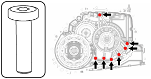
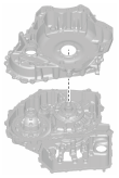
47. Assemble the converter housing using the following procedure:
|
1
|
O-ring (outer diameter approx. 15.6 mm {0.614 in}, thickness approx. 2.4 mm {0.094 in})
|
|
2
|
O-ring (outer diameter approx. 73.3 mm {2.89 in}, thickness approx. 3.0 mm {0.12 in})
|
|
3
|
Converter housing
|
|
4
|
21 bolts * (M8 x 1.25 bolt, length approx. 28 mm {1.1 in})
|
* :Of the 21 bolts, 4 are applied with sealant
- (1) Assemble new O-rings using the following procedure:
-
-
Caution
-
• If an O-ring is reused it could cause ATF leakage, therefore use a new O-ring.
- 1) Apply ATF (ATF FZ) to the new O-rings.
- 2) Assemble new O-rings in the order shown in the figure.
-
|
1
|
O-ring (outer diameter approx. 15.6 mm {0.614 in}, thickness approx. 2.4 mm {0.094 in})
|
|
2
|
O-ring (outer diameter approx. 73.3 mm {2.89 in}, thickness approx. 3.0 mm {0.12 in})
|
- (2) Remove any remaining old sealant on the contact surfaces of the transaxle case and converter housing, and degrease the contact surfaces.
-
-
Caution
-
• When degreasing and if degreaser is used, use a rag saturated with degreaser and be careful not to allow degreaser to penetrate the interior of the transaxle.
In addition, after degreasing, visually verify that there is no foreign matter (such as old sealant, cloth fibers) which has penetrated the interior of the transaxle.
- (3) Apply sealant (silicone sealant TB1217E) to the transaxle case.
-
-
Caution
-
• If sealant is applied excessively or applied to a part other than the indicated part, the O-ring could deform and the sealant could penetrate the oil passage. Apply an appropriate amount of sealant to the indicated part.
-
Note
-
• Sealant application amount (bead thickness): φ 1.8—2.5 mm {0.071—0.098 in}
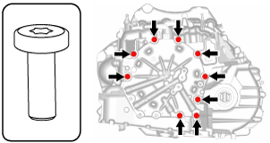
- (4) Assemble the converter housing before the applied sealant starts to harden.
-
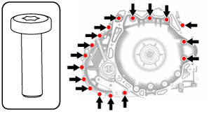
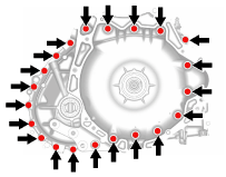
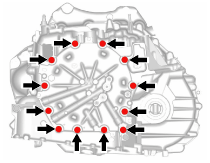
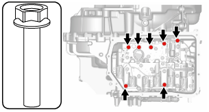
- (5) Assemble and temporarily tighten the bolts to the positions shown in the figure.
-
-
Note
-
• Bolt size: M8 x 1.25 bolt (length approx. 28 mm {1.1 in})
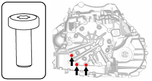
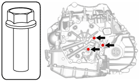
- (6) Assemble and temporarily tighten the new bolts to the positions shown in the figure.
-
-
Caution
-
• The bolts for the assembly are coated with sealant. If the bolts are reused it could cause ATF leakage, therefore use new bolts.
-
Note
-
• Bolt size: M8 x 1.25 bolt, length approx. 28 mm {1.1 in} (with sealant applied)
- (7) Tighten the bolts shown in the figure.
-
-
Tightening torque
-
19—25 N·m {2.0—2.5 kgf·m, 15—18 ft·lbf}
48. Assemble the front sun gear.
49. Assemble the rear sun gear.
50. Assemble the rear planetary gear using the following procedure:
- (1) Assemble the rear planetary gear.
-
-
Note
-
• If the rear planetary gear assembly is difficult, assembly is easier if the work is performed using the following procedure:
-
1. Rotate and adjust the rotation handle of the engine stand so that the end cover side is situated sideways.
2. While rotating the rear planetary gear, engage the splines of each drive plate of the low and reverse brake one by one, and assemble.
- (2) To verify that the rear planetary gear is securely assembled, measure the distance shown in the figure.
-
-
Note
-
• Recommended measuring instrument: Depth gauge, straight edge ruler
A :Transaxle case end (alignment surface with end cover)
B :Rear planetary gear end
-
Specification
-
28.9—30.9 mm {1.14—1.21 in}
-
• If not within the specification, remove the rear planetary gear and reassemble.
-
Note
-
- 1) Set two straight edge rulers along the alignment surface of the transaxle case with the end cover as shown in the figure.
- 2) Measure the positions (2 locations) shown in the figure using a depth gauge and calculate the average value.
-
A :Straight edge ruler
- 3) Subtract the thickness of the straight edge ruler from the average value.
51. Assemble the thrust needle bearing.
-
Note
-
• Thrust needle bearing size: Outer diameter approx. 44 mm {1.7 in}
52. Assemble the bearing race.
-
Note
-
• Bearing race size: Outer diameter approx. 41.2 mm {1.62 in}
53. Assemble the shim using the following procedure:
-
Note
-
• Shim size: Outer diameter approx. 39.8 mm {1.57 in}
- (1) Measure the total end play and select the appropriate shim. (See TOTAL END PLAY MEASUREMENT/ADJUSTMENT.)
-
-
Caution
-
• The total end play is the play (gap) in the axial direction of each planetary gear. If the total end play adjustment is not performed, it may cause damage to the thrust needle bearing between each planetary gear or other parts.
- (2) Assemble the shim selected in Step (1).
-
A :Selection
54. Assemble the end cover component using the following procedure:
|
1
|
O-ring (outer diameter approx. 15.6 mm {0.614 in}, thickness approx. 2.4 mm {0.094 in})
|
|
2
|
End cover component
|
|
3
|
12 bolts * (M8 x 1.25 bolt, length approx. 21 mm {0.83 in})
|
* :Of the 12 bolts, 3 are applied with sealant
- (1) Assemble new O-rings using the following procedure:
-
-
Caution
-
• If an O-ring is reused it could cause ATF leakage, therefore use a new O-ring.
-
Note
-
• O-ring size: Outer diameter approx. 15.6 mm {0.614 in}, thickness approx. 2.4 mm {0.094 in}
- 1) Apply ATF (ATF FZ) to the new O-rings.
- 2) Assemble the new O-rings.
-
- (2) Remove any remaining old sealant on the contact surfaces of the transaxle case and end cover, and degrease the contact surfaces.
-
-
Caution
-
• When degreasing and if degreaser is used, use a rag saturated with degreaser and be careful not to allow degreaser to penetrate the interior of the transaxle.
In addition, after degreasing, visually verify that there is no foreign matter (such as old sealant, cloth fibers) which has penetrated the interior of the transaxle.
- (3) Apply sealant (silicone sealant TB1217E) to the transaxle case.
-
-
Caution
-
• If sealant is applied excessively or applied to a part other than the indicated part, the O-ring could deform and the sealant could penetrate the oil passage. Apply an appropriate amount of sealant to the indicated part.
-
Note
-
• Sealant application amount (bead thickness): φ 0.5—1.8 mm {0.02—0.07 in}
- (4) Assemble the end cover component before the applied sealant starts to harden.
-
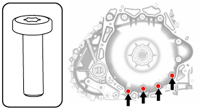
- (5) Assemble and temporarily tighten the bolts to the positions shown in the figure.
-
-
Note
-
• Bolt size: M8 x 1.25 bolt (length approx. 21 mm {0.83 in})
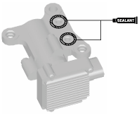
- (6) Assemble and temporarily tighten the new bolts to the positions shown in the figure.
-
-
Caution
-
• The bolts for the assembly are coated with sealant. If the bolts are reused it could cause ATF leakage, therefore use new bolts.
-
Note
-
• Bolt size: M8 x 1.25 bolt, length approx. 21 mm {0.83 in} (with sealant applied)
- (7) Tighten the bolts shown in the figure.
-
-
Tightening torque
-
19—25 N·m {2.0—2.5 kgf·m, 15—18 ft·lbf}
55. Assemble the control valve body using the following procedure:
-
Caution
-
• Do not drop or apply a shock to the control valve body. Replace the control valve body with a new one if it was dropped or received an impact.
|
1
|
O-ring (outer diameter approx. 15.6 mm {0.614 in}, thickness approx. 2.4 mm {0.094 in})
|
|
2
|
Gasket
|
|
3
|
Dowel pin
|
|
4
|
Control valve body
|
|
5
|
7 bolts (M6 x 1.0 bolt, length approx. 50 mm {2.0 in})
|
- (1) Assemble new O-rings using the following procedure:
-
-
Caution
-
• If an O-ring is reused it could cause ATF leakage, therefore use a new O-ring.
-
Note
-
• O-ring size: Outer diameter approx. 15.6 mm {0.614 in}, thickness approx. 2.4 mm {0.094 in}
- 1) Apply ATF (ATF FZ) to the new O-rings.
- 2) Assemble the new O-rings.
-
- (2) Assemble new gaskets using the following procedure:
-
-
Caution
-
• If a gasket is reused it could cause ATF leakage, therefore use a new gasket.
- 1) Apply ATF (ATF FZ) to the new gaskets.
- 2) Assemble the new gaskets.
-
- (3) Assemble the dowel pins.
-
-
Caution
-
• Do not assemble the dowel pins using a tool such as a hammer so as to prevent damaging the new part. For the dowel pin assembly, only insert the dowel pins to the transaxle case assembly hole by hand.
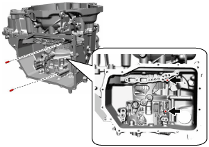
- (4) Assemble the control valve body.
-
-
Caution
-
• Assemble the control valve body straight so that force is not applied to the control valve body connector in the lateral direction.
• Assemble the control valve body so that the TCM, turbine/input shaft speed sensor, and the output shaft speed sensor do not contact the transaxle case.
A :Control valve body connector
B :TCM
C :Output shaft speed sensor
D :Turbine/input shaft speed sensor
-
Caution
-
• Adjust the manual valve and assemble the control valve body so that the parking assist lever component end is engaged with the manual valve.
A :Parking assist lever component
B :Manual valve
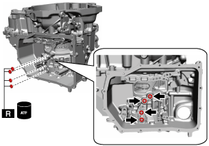
- (5) Assemble and tighten the bolts shown in the figure.
-
-
Note
-
• Bolt size: M6 x 1.0 bolt (length approx. 50 mm {2.0 in})
-
Tightening torque
-
9—10 N·m {92—101 kgf·cm, 80—88 in·lbf}
- (6) Move the manual valve in the direction shown in the figure and verify that the manual valve is engaged with the parking assist lever component end.
-
-
Note
-
• If only the excessive play area on both surfaces of the parking assist lever component and the manual valve can be moved, the manual valve and the parking assist lever component are engaged correctly.
A :Manual valve
-
• If there is a malfunction, remove the control valve body and reassemble.
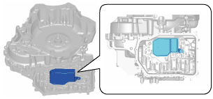
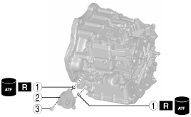
56. Assemble the oil strainer using the following procedure:
-
Caution
-
• To avoid damaging the control valve body, if there is a large amount of foreign material at the bottom of the oil pan when the oil pan is removed, replace the oil strainer with a new one.
• If there is not a large amount of foreign material at the bottom of the oil pan, the oil strainer does not have to be replaced.
|
1
|
O-ring (outer diameter approx. 29.5 mm {1.16 in}, thickness approx. 3 mm {0.1 in})
|
|
2
|
Oil strainer
|
|
3
|
Bolt (M6 x 1.0 bolt, length approx. 16 mm {0.63 in})
|
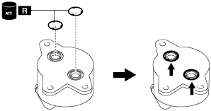
- (1) Assemble the oil strainer the following procedure:
-
-
Caution
-
• If an O-ring is reused it could cause ATF leakage, therefore use a new O-ring.
-
Note
-
• O-ring size: Outer diameter approx. 29.5 mm {1.16 in}, thickness approx. 3 mm {0.1 in})
- 1) Apply ATF (ATF FZ) to the new O-ring.
- 2) Assemble the new O-ring.
-
- (2) Assemble the oil strainer.
-
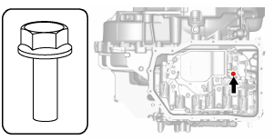
- (3) Assemble and tighten the bolt shown in the figure.
-
-
Note
-
• Bolt size: M6 x 1.0 bolt (length approx. 16 mm {0.63 in})
-
Tightening torque
-
9—10 N·m {92—101 kgf·cm, 80—88 in·lbf}
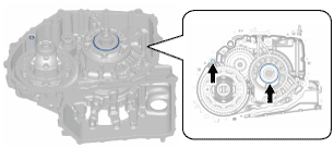
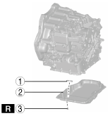
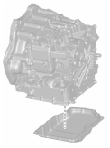
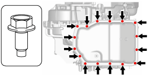
57. Assemble the oil pan and magnet using the following procedure:
|
1
|
Magnet
|
|
2
|
Oil pan
|
|
3
|
16 bolts (M6 x 1.0 bolt, length approx. 15 mm {0.59 in}*)
|
* :Length without spring washer is indicated due to bolt with spring washer. Length with spring washer is approx. 13 mm {0.51 in}.
- (1) Assemble the magnet.
-
- (2) Remove any remaining old sealant on the contact surfaces of the transaxle case and oil pan, and degrease the contact surfaces.
-
-
Caution
-
• When degreasing and if degreaser is used, use a rag saturated with degreaser and be careful not to allow degreaser to penetrate the interior of the transaxle.
In addition, after degreasing, visually verify that there is no foreign matter (such as old sealant, cloth fibers) which has penetrated the interior of the transaxle.
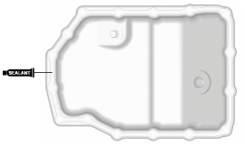
- (3) Apply sealant (silicone sealant TB1217E) to the oil pan.
-
-
Caution
-
• If sealant is applied excessively or applied to a part other than the indicated part, the sealant could penetrate the transaxle internally. Apply an appropriate amount of sealant to the indicated part.
-
Note
-
• Sealant application amount (bead thickness): φ1.9—6.7 mm {0.08—0.26 in}
- (4) Assemble the oil pan before the applied sealant starts to harden.
-
- (5) Assemble and tighten the new bolts to the positions shown in the figure.
-
-
Caution
-
• Bolts with spring washers are used for assembly. Use new bolts. If the bolts with spring washers are reused, they will loosen due to spring weakness.
-
Note
-
• Bolt size: M6 x 1.0 bolt, length approx. 15 mm {0.59 in}*
* :Length without spring washer is indicated due to bolt with spring washer. Length with spring washer is approx. 13 mm {0.51 in}.
-
Tightening torque
-
8—10 N·m {82—101 kgf·cm, 71—88 in·lbf}
58. Assemble a new oil seal using the following procedure:
-
Caution
-
• If an oil seal is reused it could cause ATF leakage, therefore use a new oil seal.
- (1) Apply ATF (ATF FZ) to the engagement area of the new oil seal and transaxle case.
- (2) Apply ATF (ATF FZ) to the engagement area of the new oil seal and connector.
- (3) Assemble the new oil seal to the position shown in the figure using the SST.
-
A :-0.5—1.5 mm {-0.01—0.05 in}
59. Assemble a new oil seal using the following procedure:
-
Caution
-
• If an oil seal is reused it could cause ATF leakage, therefore use a new oil seal.
-
Note
-
• Oil seal size: Outer diameter approx. 56 mm {2.2 in}
- (1) Apply ATF (ATF FZ) to the engagement area of the new oil seal and transaxle case.
- (2) Apply ATF (ATF FZ) to the lip of the new oil seal.
- (3) Assemble the new oil seal to the position shown in the figure using the SST.
-
A :0.5 mm {0.02 in}
B :0.5 mm {0.02 in}
60. Assemble a new oil seal using the following procedure:
-
Caution
-
• If an oil seal is reused it could cause ATF leakage, therefore use a new oil seal.
-
Note
-
• Oil seal size: Outer diameter approx. 56 mm {2.2 in}
- (1) Apply ATF (ATF FZ) to the engagement area of the new oil seal and converter housing.
- (2) Apply ATF (ATF FZ) to the lip of the new oil seal.
- (3) Assemble the new oil seal to the position shown in the figure using the SST.
-
A :0.5 mm {0.02 in}
B :0.5 mm {0.02 in}
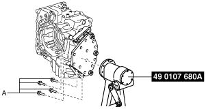
61. Remove the SSTs from the transaxle using the following procedure:
-
Caution
-
• When removing the transaxle from the SST (engine stand) using chain hoists, be careful not to allow the transaxle to contact the SST (engine stand). If the transaxle contacts the SST, verify the areas which were contacted and replace damaged parts with new ones.
- (1) Assemble the SSTs using part number: 9YA02 1015, or M10 x 1.5 bolt (length 35 mm {1.4 in}).
-
A :Part number: 9YA02 1015, or M10 x 1.5 bolt, length 35 mm {1.4 in}
-
Tightening torque
-
38—52 N·m {3.9—5.3 kgf·m, 29—38 ft·lbf}
- (2) Using chain hoists, remove the transaxle from the SST (engine stand).
-
-
Caution
-
• When removing the transaxle from the SST (engine stand) using chain hoists, be careful not to allow the transaxle to contact the SST (engine stand). If the transaxle contacts the SST, verify the areas which were contacted and replace damaged parts with new ones.
A :Part number: 9YA02 A220, or M12 x 1.75 bolt, length 40 mm {1.6 in}
- (3) Remove the SSTs.
-
A :Part number: 9YA02 1015, or M10 x 1.5 bolt, length 35 mm {1.4 in}
- (4) Disassemble the SST.
-
A :Part number: 9YA02 1440, or M14 x 1.5 bolt, length 100 mm {3.94 in}
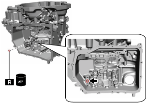
62. Assemble a new hose clamp using the following procedure:
-
Caution
-
• If a hose clamp is reused it could cause ATF leakage, therefore use a new hose clamp.
- (1) Assemble the new hose clamp to the position shown in the figure.
-
-
Caution
-
• Assemble the hose clamp tab to within the range shown in the figure.
A :210°
- (2) Verify that the hose clamp is assembled to within the position shown in the figure.
-
-
Caution
-
• Verify that the hose clamp does not contact the oil seal flange.
A :Hose clamp assembly range
B :Hose clamp
C :Oil seal flange
-
• If not within the range, adjust so that the hose clamp assembly position is within the range.
63. Assemble the dipstick using the following procedure:
|
1
|
O-ring (outer diameter approx. 16.6 mm {0.654 in}, thickness approx. 2.4 mm {0.094 in})
|
|
2
|
Dipstick
|
|
3
|
Bolt (M6 x 1.0 bolt, length approx. 16 mm {0.63 in})
|
- (1) Assemble a new O-ring using the following procedure:
-
-
Caution
-
• If an O-ring is reused it could cause ATF leakage, therefore use a new O-ring.
-
Note
-
• O-ring size: Outer diameter approx. 16.6 mm {0.654 in}, thickness approx. 2.4 mm {0.094 in})
- 1) Apply ATF (ATF FZ) to the new O-ring.
- 2) Assemble the new O-ring.
-
- (2) Assemble the dipstick.
-
- (3) Assemble and tighten the bolt shown in the figure.
-
-
Note
-
• Bolt size: M6 x 1.0 bolt (length approx. 16 mm {0.63 in})
-
Tightening torque
-
8—11 N·m {82—112 kgf·cm, 71—97 in·lbf}
64. Assemble the oil cooler using the following procedure:
|
1
|
O-ring (outer diameter approx. 24.4 mm {0.961 in}, thickness approx. 2.4 mm {0.094 in})
|
|
2
|
Oil cooler
|
|
3
|
3 bolts (M8 x 1.25 bolt, length approx. 23.5 mm {0.925 in})
|
- (1) Assemble new O-rings using the following procedure:
-
-
Caution
-
• If an O-ring is reused it could cause ATF leakage, therefore use a new O-ring.
-
Note
-
• O-ring size: Outer diameter approx. 24.4 mm {0.961 in}, thickness approx. 2.4 mm {0.094 in}
- 1) Apply ATF (ATF FZ) to the new O-rings.
- 2) Assemble the new O-rings.
-
- (2) Assemble the oil cooler.
-
- (3) Assemble and tighten the bolts shown in the figure.
-
-
Note
-
• Bolt size: M8 x 1.25 bolt (length approx. 23.5 mm {0.925 in})
-
Tightening torque
-
22—27 N·m {2.3—2.7 kgf·m, 17—19 ft·lbf}
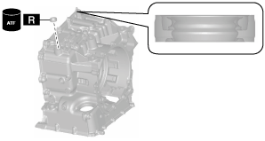
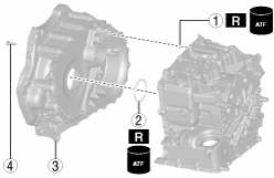
65. Assemble the torque converter using the following procedure:
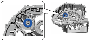
- (1) Apply ATF (ATF FZ) to the stator shaft end of the oil pump shown in the figure.
-
-
Caution
-
• Accurately perform the procedure to protect the internal parts of the torque converter.
- (2) Assemble the torque converter so that the two surfaces of the notch on the end of the torque converter engage the inner rotor of the oil pump.
-
- (3) To verify that the torque converter is securely assembled, measure the distance shown in the figure.
-
-
Note
-
• Recommended measuring instrument: Depth gauge, straight edge ruler
A :Converter housing end (alignment surface with engine)
B :Torque converter stud bolt surface
-
Specification
-
17.2 mm {0.677 in} or more
-
• If not within the specification, remove the torque converter and reassemble.
-
Note
-
- 1) Set two straight edge rulers along the alignment surface of the converter housing with the engine as shown in the figure.
- 2) Measure the positions (2 locations) shown in the figure using a depth gauge and calculate the average value.
-
A :Straight edge ruler
- 3) Subtract the thickness of the straight edge ruler from the average value.
66. Assemble and tighten the stud bolts.
-
Tightening torque
-
15.0—25.0 N·m {1.6—2.5 kgf·m, 12—18 ft·lbf}
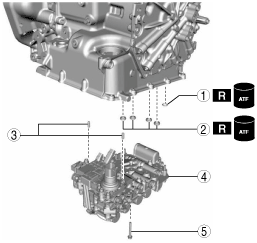
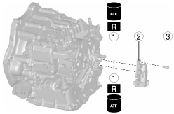
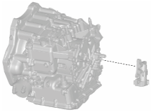
67. Assemble the electric AT oil pump using the following procedure: (Only vehicles with i-stop)
-
Caution
-
• Do not drop or apply a shock to the electric AT oil pump. Replace the electric AT oil pump with a new one if it was dropped or received an impact.
• Do not disassemble the electric AT oil pump. Replace the electric AT oil pump if it has been disassembled.
• Verify that there is no sealant or foreign matter in the electrical AT oil pump and transaxle. Otherwise, it could cause a malfunction.
• Be careful not to scratch or damage the aligning surfaces of the electric AT oil pump and end cover and the O-ring installation area so as not to cause ATF leakage.
|
1
|
O-ring (outer diameter approx. 15.6 mm {0.614 in}, thickness approx. 2.4 mm {0.094 in})
|
|
2
|
Electric AT oil pump
|
|
3
|
3 bolts (M8 x 1.25 bolt, length approx. 25 mm {0.98 in})
|
- (1) Assemble new O-rings using the following procedure:
-
-
Caution
-
• If an O-ring is reused it could cause ATF leakage, therefore use a new O-ring.
-
Note
-
• O-ring size: Outer diameter approx. 15.6 mm {0.614 in}, thickness approx. 2.4 mm {0.094 in}
- 1) Apply ATF (ATF FZ) to the new O-rings.
- 2) Assemble the new O-rings.
-
- (2) Remove any remaining old sealant on the contact surfaces of the end cover and electric AT oil pump, and clean degrease the contact surfaces.
-
-
Caution
-
• When degreasing and if degreaser is used, use a rag saturated with degreaser and be careful not to allow degreaser to penetrate the oil passage.
In addition, after degreasing, visually verify that there is no foreign matter (such as old sealant, cloth fibers) which has penetrated the oil passage.
- (3) Apply sealant (silicone sealant TB1217E) to the electric AT oil pump.
-
-
Caution
-
• If sealant is applied excessively or applied to a part other than the indicated part, the O-ring could deform and the sealant could penetrate the oil passage. Apply an appropriate amount of sealant to the indicated part.
-
Note
-
• Sealant application amount (bead thickness): φ 0.5—1.5 mm {0.02—0.05 in}
- (4) Assemble the electric AT oil pump before the applied sealant starts to harden.
-
- (5) Assemble and tighten the bolts shown in the figure.
-
-
Note
-
• Bolt size: M8 x 1.25 bolt (length approx. 25 mm {0.98 in})
-
Tightening torque
-
19—25 N·m {2.0—2.5 kgf·m, 15—18 ft·lbf}