 |
am2zzw00005310
ENGINE REMOVAL/INSTALLATION [MZR 1.3, MZR 1.5]
id0110e1800400
1. Complete the "Fuel Line Safety Procedure", and remove the fuel pump relay. (See BEFORE SERVICE PRECAUTION [MZR 1.3, MZR 1.5].)
2. Remove the battery and the battery tray. (See BATTERY REMOVAL/INSTALLATION [MZR 1.3, MZR 1.5].)
3. Drain the engine coolant. (See ENGINE COOLANT REPLACEMENT [MZR 1.3, MZR 1.5].)
4. Drain the ATF (ATX), CVT fluid (CVT) or transaxle oil (MTX). (See AUTOMATIC TRANSAXLE FLUID (ATF) REPLACEMENT [FN4A-EL] (ATX).) (See CVT (CONTINUOUSLY VARIABLE TRANSAXLE) FLUID REPLACEMENT [DJVA-EL] (CVT).) (See TRANSAXLE OIL REPLACEMENT [F35M-R] (MTX).)
5. Remove the front wheels and tires (See GENERAL PROCEDURES (SUSPENSION).)
6. Disconnect the radiator hose.
7. Remove the fresh-air duct and the air cleaner as a single unit, the evaporative hose, and the air hose. (See INTAKE-AIR SYSTEM REMOVAL/INSTALLATION [MZR 1.3, MZR 1.5].)
8. Disconnect the fuel hose. (See FUEL INJECTOR REMOVAL/INSTALLATION [MZR 1.3, MZR 1.5].)
9. Remove the drive belt. (See DRIVE BELT REMOVAL/INSTALLATION [MZR 1.3, MZR 1.5].)
10. Set the cooler pipe and the cooler hose (LO) out of the way. (With A/C) (See REFRIGERANT LINE REMOVAL/INSTALLATION [MZR 1.3, MZR 1.5].)
11. Remove the generator. (See GENERATOR REMOVAL/INSTALLATION [MZR 1.3, MZR 1.5].)
12. Remove the A/C compressor with the pipes still connected. (With A/C) (See A/C COMPRESSOR REMOVAL/INSTALLATION [MZR 1.3, MZR 1.5].)
13. Disconnect the front drive shafts. (See DRIVE SHAFT REMOVAL/INSTALLATION [MZR1.3, MZR 1.5].)
14. Disconnect the ATF hose, selector cable, and wiring harness. (ATX) (See AUTOMATIC TRANSAXLE REMOVAL/INSTALLATION [FN4A-EL].)
15. Disconnect the selector cable, and wiring harness. (CVT) (See CVT (CONTINUOUSLY VARIABLE TRANSAXLE) REMOVAL/INSTALLATION [DJVA-EL].)
16. Disconnect the shift cable. (MTX) (See MANUAL TRANSAXLE REMOVAL/INSTALLATION [F35M-R].)
17. Remove the clutch release cylinder with the pipe still connected. (MTX) (See CLUTCH RELEASE CYLINDER REMOVAL/INSTALLATION [F35M-R].)
18. Disconnect the vacuum hose and the heater hose.
19. Disconnect the wiring harness from the engine side.
20. Remove the middle pipe or the presilencer. (See EXHAUST SYSTEM REMOVAL/INSTALLATION [MZR 1.3, MZR 1.5].)
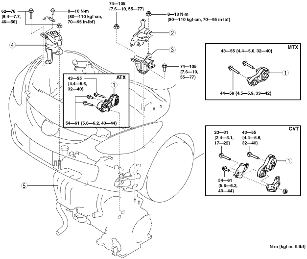
21. Remove in the order indicated in the table.
22. Install in the reverse order of removal.
23. Start the engine. and inspect and adjust the following.
am2zzw00005310
|
|
1
|
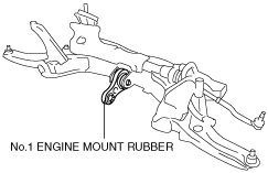
No.1 Engine mount rubber
|
|
2
|
Battery tray bracket
|
|
3
|
No.4 Engine mount rubber
|
|
4
|
No.3 Engine mount
|
|
5
|
Engine, transaxle
|
No.1 Engine Mount Removal Note
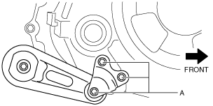
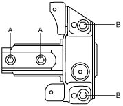
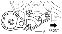
1. Remove the No.1 engine mount installation bolt (A) from below the vehicle.
ATX
am2zzw00004166
|
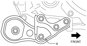
CVT
am2zzw00005311
|
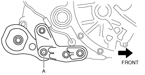
MTX
am2zzw00006220
|
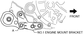
2. Remove the No.1 engine mount rubber and the front crossmember as a single unit. (See FRONT CROSSMEMBER REMOVAL/INSTALLATION.)
am2zzw00006221
|
No.3 Engine Mount, No.4 Engine Mount Rubber Removal Note
am2zzw00004168
|
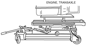
1. Secure the engine and the transaxle using an engine jack.
am2zzw00002587
|
No.3 Engine Mount, No.4 Engine Mount Rubber Installation Note
1. Secure the engine and the transaxle using an engine jack.
am2zzw00002587
|
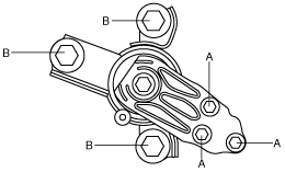
2. Install the No.3 engine mount, and then temporarily tighten the installation bolts and nuts.
3. Tighten the installation bolts and nuts by order of A,B.
am2zzw00001797
|
4. Install the No.4 engine mount rubber, and then temporarily tighten the installation bolts and nuts.
5. Tighten the installation bolts and nuts by order of A,B.
am2zzw00001798
|
6. Remove the engine jack and attachment.
No.1 Engine Mount Installation Note
1. Install the front crossmember component. (See FRONT CROSSMEMBER REMOVAL/INSTALLATION.)
2. Tighten the No.1 engine mount installation bolt (A).
ATX
am2zzw00004166
|
CVT
am2zzw00004237
|
MTX
am2zzw00004201
|