 |
adejjw00002625
EXPANSION VALVE REMOVAL
id071100817100
L.H.D.
1. Disconnect the negative battery cable.
2. Collect the refrigerant. (See REFRIGERANT CHARGING.)
3. Remove the air cleaner installation bolt and slide the air cleaner component aside.
4. Remove the cooler hose (LO) installation nut, and then remove the cooler hose (LO) bracket from the vehicle stud bolt.
adejjw00002625
|
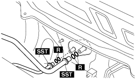
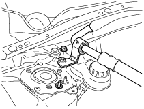
5. Using the SSTs (49 B061 014, 49 G061 001) disconnect the cooler pipe and cooler hose from the A/C unit while not allowing the remaining compressor oil in the A/C compressor and pipes to spill. (See REFRIGERANT LINE REMOVAL/INSTALLATION [MZR 1.3, MZR 1.5].) (See REFRIGERANT LINE REMOVAL/INSTALLATION [MZ-CD 1.6].)
adejjw00001427
|
6. Remove the following parts:
7. Disconnect the evaporator temperature sensor connector.
8. Remove the evaporator temperature sensor wiring harness clip.
9. Disconnect the power MOS FET connector. (full-auto air conditioner)
10. Disconnect the resistor connector. (manual air conditioner)
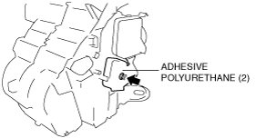
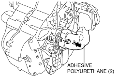
11. Make a hole in the position shown in the figure for the adhesive polyurethane (2) and remove the outlet pipe installation bolt.
am2zzw00001828
|
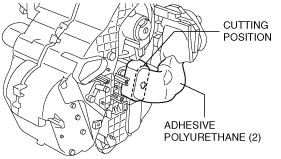
12. Cut the adhesive polyurethane (2) near the contact surfaces of the expansion valve and outlet pipe, and tear it off.
am2zzw00001042
|
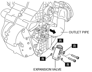
13. Slide the outlet pipe to the right while being careful not to allow remaining compressor oil in the outlet pipe and expansion valve to spill.
am2zzw00001043
|
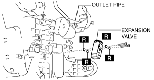
14. Remove the expansion valve installation bolts.
15. Remove the expansion valve while being careful not to allow the remaining compressor oil in the expansion valve and evaporator to spill.
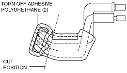
16. Tear off the adhesive polyurethane (2) from the expansion valve.
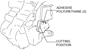
17. Cut the adhesive polyurethane (2) as shown in the figure and remove the adhesive polyurethane (2) from the outlet pipe near the expansion valve.
am2zzw00001044
|
R.H.D.
1. Disconnect the negative battery cable.
2. Collect the refrigerant. (See REFRIGERANT CHARGING.)
3. Remove the air cleaner installation bolt and slide the air cleaner component aside.
4. Remove the cooler hose (LO) installation nut, and then remove the cooler hose (LO) bracket from the vehicle stud bolt.
adejjw00002625
|
5. Using the SSTs (49 B061 014, 49 G061 001) disconnect the cooler pipe and cooler hose from the A/C unit while not allowing the remaining compressor oil in the A/C compressor and pipes to spill. (See REFRIGERANT LINE REMOVAL/INSTALLATION [MZR 1.3, MZR 1.5].) (See REFRIGERANT LINE REMOVAL/INSTALLATION [MZ-CD 1.6].)
adejjw00001427
|
6. Remove the following parts:
7. Remove the clutch pedal installation nut and slide the clutch pedal upward. (MTX) (See CLUTCH PEDAL REMOVAL/INSTALLATION [F35M-R].) (See CLUTCH PEDAL REMOVAL/INSTALLATION [B65M-R].)
8. Remove the air mix actuator. (full-auto air conditioner) (See AIR MIX ACTUATOR REMOVAL/INSTALLATION [FULL-AUTO AIR CONDITIONER].)
9. Put a hole in the adhesive polyurethane (2) in the position shown in the figure and remove the outlet pipe installation bolt.
am2zzw00001833
|
10. Cut the adhesive polyurethane (2) near the contact surfaces of the expansion valve and outlet pipe, and tear it off.
am2zzw00001845
|
11. Slide the outlet pipe to the right while being careful not to allow remaining compressor oil in the outlet pipe and expansion valve to spill.
am2zzw00001846
|
12. Remove the expansion valve installation bolts.
13. Remove the expansion valve while being careful not to allow the remaining compressor oil in the expansion valve and evaporator to spill.
14. Tear off the adhesive polyurethane (2) from the expansion valve.
15. Cut the adhesive polyurethane (2) as shown in the figure and remove the adhesive polyurethane (2) from the outlet pipe near the expansion valve.
am2zzw00002016
|