 |
am3zzw00010437
SUPPLY PUMP REMOVAL/INSTALLATION [MZ-CD 1.6 (Y6)]
id0114c3805700
EURO4 Emission Level
1. Complete the “BEFORE SERVICE PRECAUTION”. (See BEFORE SERVICE PRECAUTION [MZ-CD 1.6 (Y6)].)
2. Remove the battery cover. (See BATTERY REMOVAL/INSTALLATION[MZ-CD 1.6 (Y6)].)
3. Disconnect the negative battery cable. (See BATTERY REMOVAL/INSTALLATION[MZ-CD 1.6 (Y6)].)
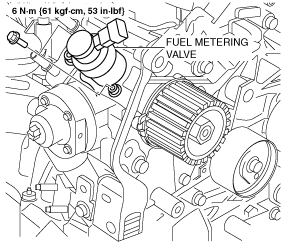
4. Remove the fuel metering valve. (See Fuel Metering Valve Removal/Installation Note.)
5. Remove the engine cover. (See ENGINE COVER REMOVAL/INSTALLATION [MZ-CD 1.6 (Y6) (EURO4 emission level)].)
6. Remove the aerodynamic under cover No.2. (See AERODYNAMIC UNDER COVER NO.2 REMOVAL/INSTALLATION.)
7. Remove the splash shield (RH). (See SPLASH SHIELD REMOVAL/INSTALLATION.)
8. Drain the engine coolant. (See ENGINE COOLANT REPLACEMENT [MZ-CD 1.6 (Y6)].)
9. Remove the EGR valve. (See EGR VALVE REMOVAL/INSTALLATION [MZ-CD 1.6 (Y6)].)
10. Remove the glow plug cord stay. (See GLOW PLUG REMOVAL/INSTALLATION [MZ-CD 1.6 (Y6)].)
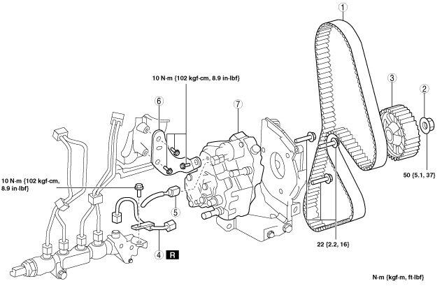
11. Remove in the order indicated in the table.
12. Install in the reverse order of removal.
13. Complete the “AFTER SERVICE PRECAUTION”. (See AFTER SERVICE PRECAUTION [MZ-CD 1.6 (Y6)].)
am3zzw00010437
|
|
1
|
Timing belt
|
|
2
|
Supply pump pulley nut
|
|
3
|
Supply pump pulley
|
|
4
|
Injection pipe
|
|
5
|
Connector
|
|
6
|
Supply pump bracket
|
|
7
|
Supply pump
|
Supply Pump Pulley Nut Removal Note
1. Using the SSTs, hold the supply pump pulley nut and remove the retaining nut.
am3zzw00010438
|
Supply Pump Pulley Removal Note
1. Using the SST, remove the supply pump pulley.
am3zzw00010439
|
Supply Pump Pulley Nut Installation Note
1. Using the SSTs, tighten the supply pump pulley retaining nut.
am3zzw00010438
|
EURO5 Emission Level
1. Disconnect the negative battery cable. (See BATTERY REMOVAL/INSTALLATION[MZ-CD 1.6 (Y6)].)
2. Remove the fuel metering valve. (See FUEL METERING VALVE REMOVAL/INSTALLATION [MZ-CD 1.6 (Y6)].)
3. Remove the following parts:
4. Set the cooler hose (LO) out of the way. (See REFRIGERANT LINE REMOVAL/INSTALLATION.)
5. Remove the timing belt. (See TIMING BELT REMOVAL/INSTALLATION [MZ-CD 1.6 (Y6) (EURO5 emission level)].)
6. Remove and dispose of the injection pipe (supply pump side). (See COMMON RAIL REMOVAL/INSTALLATION [MZ-CD 1.6 (Y6)].)
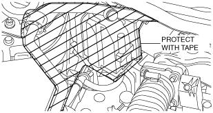
7. The position shown in figure is protected with the tape.
am3zzw00012937
|
8. Remove the nut using the SST as shown in the figure.
am3zzw00012938
|
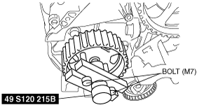
9. Remove the bolt as shown in the figure.
am3zzw00012939
|
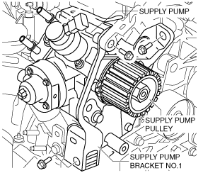
10. Remove the supply pump and supply pump bracket No.1 and supply pump pulley as single unit.
am3zzw00012940
|
11. Install the SST as shown in the figure.
am3zzw00012941
|
12. Remove the supply pump pulley.
13. Remove the supply pump.
am3zzw00012942
|
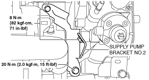
14. Remove the supply pump bracket No.2.
15. Install in the reverse order of removal.
Fuel Metering Valve Removal/Installation Note
am2zzw00007209
|