|
1
|
INSPECT BATTERY VOLTAGE
• Is the battery positive terminal voltage normal?
|
Yes
|
Inspect for normal connection of the battery terminals.
Go to the next step.
|
|
No
|
Charge or replace the battery, then go to Step 7. (except MZR 2.0 DISI i-stop)
Charge or replace the main battery, then go to Step 7. (MZR 2.0 DISI i-stop)
|
|
2
|
INSPECT BATTERY GRAVITY
• Is battery specific gravity as specified?
|
Yes
|
Go to the next step.
|
|
No
|
Replace the battery, then go to Step 7. (except MZR 2.0 DISI i-stop)
Replace the main battery, then go to Step 7. (MZR 2.0 DISI i-stop)
|
|
3
|
INSPECT CHARGING SYSTEM
• Are the generator and the drive belt tensions normal?
|
Yes
|
Go to the next step.
|
|
No
|
Replace the generator and/or drive belt if necessary.
Go to Step 7.
|
|
4
|
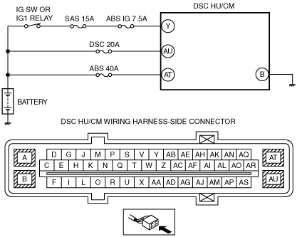
INSPECT ABS FUSE CONDITION
• Is the ABS fuse (ABS 40A/DSC 20A/SAS 15A/ABS IG 7.5A) normal?
|
Yes
|
Go to the next step.
|
|
No
|
Replace the fuse, then go to Step 7.
|
|
5
|
INSPECT DSC HU/CM POWER SUPPLY FOR OPEN CIRCUIT
• Disconnect the DSC HU/CM connectors.
• Switch the ignition to ON.
• Measure the voltage between following connector terminals of the DSC HU/CM (vehicle harness-side) and body ground:
-
― DSC HU/CM: Y—Body ground
― DSC HU/CM: AU—Body ground
― DSC HU/CM: AT—Body ground
• Is the voltage 10 V or more?
|
Yes
|
Go to the next step.
|
|
No
|
Repair or replace the wiring harness, then go to Step 7.
|
|
6
|
INSPECT DSC HU/CM GROUND FOR POOR GROUND OR OPEN CIRCUIT
• Switch the ignition to off.
• Measure the resistance between the DSC HU/CM terminal B (vehicle harness-side) and body ground.
• Is the resistance within 0—1 ohm?
|
Yes
|
Go to the next step.
|
|
No
|
If there is open circuit:
• Repair or replace the wiring harness, then go to the next step.
If resistance is not within specification:
• Repair or replace the poor ground part, then go to the next step.
|
|
7
|
VERIFY THAT THE SAME DTC IS NOT PRESENT
• Reconnect all disconnected connectors.
• Clear the DTCs from the memory.
• Start the engine and drive the vehicle at 20 km/h {12 mph} or more.
• Are the same DTCs present?
|
Yes
|
Repeat the inspection from Step 1.
|
|
No
|
Go to the next step.
|
|
8
|
VERIFY THAT NO OTHER DTCS ARE PRESENT
• Are any other DTCs output?
|
Yes
|
Go to the applicable DTC inspection.
|
|
No
|
DTC troubleshooting completed.
|