|
1
|
-
Note
-
• The following test should be perform on the advanced keyless entry and push button start system. If not equipped, go to the next step.
Insert the emergency key in the emergency slot and start the engine.
Does the engine start?
|
Yes
|
Inspect the advanced keyless entry and push button start system.
Repair or replace the malfunctioning part according to the inspection results.
|
|
No
|
Go to the next step.
|
|
2
|
-
Note
-
• The following test should be performed for vehicles with immobilizer system. Go to Step 7 for vehicles without immobilizer system.
Do the following conditions appear?
• The engine is not completely started.
• PCM DTC P1260:00 is displayed.
|
Yes
|
Both conditions appear:
• Go to Step 5.
|
|
No
|
Either or other condition appears:
• Go to the next step.
|
|
3
|
Inspect the connection of coil antenna connector.
Is the coil antenna connector securely connected to the coil antenna?
|
Yes
|
Go to the next step.
|
|
No
|
Connect the coil antenna connector securely.
Return to Step 1.
|
|
4
|
Does the security light flash?
|
Yes
|
Go to the next step.
|
|
No
|
Inspect the instrument cluster and related wiring harness.
Repair or replace the malfunctioning part according to the inspection results.
|
|
5
|
Retrieve the DTC for immobilizer system.
Is there any DTC present?
|
Yes
|
Go to the appropriate DTC inspection.
|
|
No
|
Go to the next step.
|
|
6
|
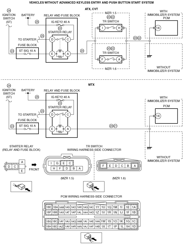
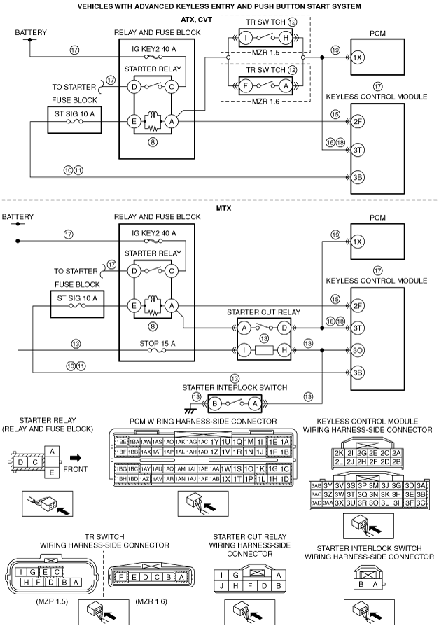
Inspect the wiring harnesses between the following terminals and related connectors:
• With advanced keyless entry and push button start system:
-
― Coil antenna terminal A—Keyless control module terminal 2H
― Coil antenna terminal B—Keyless control module terminal 2G
― PCM terminal 1AE—Keyless control module terminal 2K
― PCM terminal 1AI—Keyless control module terminal 2L
• Without advanced keyless entry and push button start system:
-
― Coil antenna terminal A—Instrument cluster terminal 2Q
― Coil antenna terminal B—Instrument cluster terminal 2M
― PCM terminal 1AE—Instrument cluster terminal 2B
― PCM terminal 1AI—Instrument cluster terminal 2D
Is there any malfunction?
|
Yes
|
Repair or replace the suspected wiring harness and connector.
|
|
No
|
Go to the next step.
|
|
7
|
Inspect the following:
• Battery connection
• Selector lever is in P or N position (ATX, CVT)
Is there any malfunction?
|
Yes
|
Repair or replace the malfunctioning part according to the inspection results.
Repeat Step 7.
|
|
No
|
With advanced keyless and push button start system:
• Go to the next step.
Without advanced keyless and push button start system:
• Go to Step 20.
|
|
8
|
Inspect the starter relay.
Is the starter relay normal?
|
Yes
|
Go to the next step.
|
|
No
|
Replace the starter relay.
|
|
9
|
Remove the starter relay.
Switch the ignition to ON (engine off).
Measure the voltage of the connector terminal (primary coil power supply) on the starter relay wiring harness.
Is the voltage B+?
|
Yes
|
Go to Step 12.
|
|
No
|
Go to the next step.
|
|
10
|
Switch the ignition to off.
Disconnect the keyless control module connector.
Inspect for continuity between keyless control module terminal 3B (wiring harness-side) and starter relay terminal (primary coil power supply).
Is there continuity?
|
Yes
|
Go to the next step.
|
|
No
|
Repair or replace the suspected wiring harness and connector.
|
|
11
|
Inspect for continuity between keyless control module terminal 3B (wiring harness-side) and body ground.
Is there continuity?
|
Yes
|
Repair or replace the suspected wiring harness and connector.
|
|
No
|
Replace the keyless control module.
|
|
12
|
Install the starter relay.
Short the following terminals using a jumper wire:
• Starter interlock switch connector (2-pin) (MTX)
• TR switch terminals A and F (ATX)
• TR switch terminals H and I (CVT)
Switch the ignition to start.
Does the engine start?
|
Yes
|
Go to the next step. (MTX)
Replace the TR switch. (ATX, CVT)
|
|
No
|
Go to Step 14.
|
|
13
|
Connect the all disconnected connectors.
Inspect the keyless control module terminal 3O voltage.
Is the voltage following?
• Clutch pedal depressed: below 1.0V
• Clutch pedal released: B+
|
Yes
|
Inspect the following:
• Wiring harness between battery positive terminal and starter cut relay terminal I
Repair or replace the malfunctioning part according to the inspection results.
|
|
No
|
Inspect the following:
• Wiring harness between starter cut relay terminal H and starter interlock switch terminal A
• Wiring harness between starter interlock switch terminal B and body ground
• Starter interlock switch (stuck)
Repair or replace the malfunctioning part according to the inspection results.
|
|
14
|
Is the starter relay operation sound heard when the engine starting procedure is performed in Step 12?
|
Yes
|
Go to the next step.
|
|
No
|
Go to Step 18.
|
|
15
|
Switch the ignition to ON (engine off).
Measure the voltage at keyless control module terminal 2F (wiring harness-side).
Is the voltage B+?
|
Yes
|
Go to the next step.
|
|
No
|
Repair or replace the suspected wiring harness and connector.
|
|
16
|
Switch the ignition to off.
Disconnect the keyless control module and starter cut relay (MTX) or TR switch (ATX, CVT) connectors.
Inspect for continuity between the following terminals:
• Keyless control module terminal 3T—Starter cut relay terminal D (MTX)
• Keyless control module terminal 3T—TR switch terminal A (ATX)
• Keyless control module terminal 3T—TR switch terminal H (CVT)
Is there continuity?
|
Yes
|
Go to the next step.
|
|
No
|
Repair or replace the suspected wiring harness and connector.
|
|
17
|
Inspect the following:
• Starter
• Wiring harness between the starter and ground
• Starter power supply (from battery through secondary starter relay, to starter)
Is there any malfunction?
|
Yes
|
Repair or replace the malfunctioning part according to the inspection results.
|
|
No
|
Replace the keyless control module.
|
|
18
|
Switch the ignition to off.
Disconnect the keyless control module and starter cut relay (MTX) or TR switch (ATX, CVT) connectors.
Inspect for continuity between the following terminals:
• Keyless control module terminal 3T—Starter cut relay terminal D (MTX)
• Keyless control module terminal 3T—TR switch terminal A (ATX)
• Keyless control module terminal 3T—TR switch terminal H (CVT)
Is there continuity?
|
Yes
|
Go to the next step.
|
|
No
|
Repair or replace the suspected wiring harness and connector.
|
|
19
|
Disconnect the PCM connector (with starter cut relay (MTX) or TR switch (ATX, CVT) connectors left removed).
Inspect for continuity between the following terminals:
• Starter cut relay terminal D—PCM terminal 1X (MTX)
• TR switch terminals A—PCM terminal 1X (ATX)
• TR switch terminals H—PCM terminal 1X (CVT)
Is there continuity?
|
Yes
|
Go to Step 27.
|
|
No
|
Repair or replace the suspected wiring harness and connector.
|
|
20
|
Is there continuity between PCM terminal 1X (wiring harness-side) and starter relay with P or N position (ATX, CVT)/clutch pedal depressed (MTX)?
|
Yes
|
Go to the next step.
|
|
No
|
Repair or replace the suspected wiring harness and connector.
|
|
21
|
Selector lever is in P or N position. (ATX, CVT)
Depressed the clutch pedal. (MTX)
Is a clicking sound heard from the starter relay when the switch the ignition to start?
|
Yes
|
Go to Step 25.
|
|
No
|
ATX, CVT:
• Go to the next step.
MTX:
• Inspect the wiring harness between starter relay terminal A and PCM terminal 1X for an open or short circuit. (vehicles with immobilizer system)
• Inspect the wiring harness between starter relay terminal A and body ground for an open or short circuit. (vehicles without immobilizer system)
-
― If there is any malfunction:
-
• Repair or replace the suspected wiring harness and connector.
― If there is no malfunction:
-
• Go to Step 23.
|
|
22
|
Perform the PID/DATA Monitor and Record Procedure and access the TR PID.
Is the TR PID indicated P/N when selecting the P or N position?
|
Yes
|
Go to the next step.
|
|
No
|
Inspect the following:
• TR switch is adjusted properly.
• Open or short circuit between TR switch and PCM terminal 1X. (vehicles with immobilizer system)
• Open circuit between TR switch and body ground. (vehicles without immobilizer system)
Repair or replace the malfunctioning part according to the inspection results.
Repeat Step 21.
|
|
23
|
Inspect the starter relay and the following wiring harnesses:
• Between starter relay and PCM
• Between starter relay and ignition switch
Is there any malfunction?
|
Yes
|
Repair or replace the malfunctioning part according to the inspection results.
Repeat Step 21.
|
|
No
|
Go to the next step.
|
|
24
|
Inspect the ignition switch and related wiring harnesses.
Is there any malfunction?
|
Yes
|
Repair or replace the malfunctioning part according to the inspection results.
Repeat Step 21.
|
|
No
|
Go to the next step.
|
|
25
|
Inspect the wiring harness between the following:
• Starter relay and battery
• Starter relay and starter
Is there any malfunction?
|
Yes
|
Repair or replace the suspected wiring harness.
|
|
No
|
Go to the next step.
|
|
26
|
Inspect the starting system.
Is there any malfunction?
|
Yes
|
Repair or replace the malfunctioning part according to the inspection results.
|
|
No
|
Go to the next step.
|
|
27
|
Inspect for seized/hydro locked engine or flywheel (MTX)/drive plate (ATX, CVT).
Is the engine seized or hydro locked?
|
Yes
|
Repair or replace the malfunctioning part according to the inspection results.
|
|
No
|
Go to the next step.
|
|
28
|
Perform the DTC Reading Procedure.
Are any continuous memory DTCs present?
|
Yes
|
DTC is displayed:
• Go to the appropriate DTC inspection.
Communication error message is displayed:
• Inspect the following:
-
― Open circuit in wiring harness between main relay terminal B and PCM terminal 1AJ
― Open circuit in wiring harness between main relay terminal C and PCM terminal 1BB, 1BE and 1BF
― Main relay is stuck open
― Open or short circuit in wiring harness between DLC-2 and PCM terminals 1AE and 1AI
― Open or poor PCM ground circuit
― Poor connection of vehicle body ground
• Repair or replace the malfunctioning part according to the inspection results.
|
|
No
|
Go to the next step.
|
|
29
|
Perform the KOEO self test.
Are there any continuous memory KOEO DTCs displayed?
|
Yes
|
Go to the appropriate DTC inspection.
|
|
No
|
Inspect the following:
• START circuit in ignition switch
• Open circuit in wiring harness between ignition switch and starter
Repair or replace the malfunctioning part according to the inspection results.
|
|
30
|
Verify the test results.
• If malfunction remains, inspect related Service information perform repair or diagnosis.
-
― If vehicle repaired, troubleshooting completed.
|