|
am3zzw00007046
ENGINE REMOVAL/INSTALLATION [MZR-CD 2.2]
id0110f2800400
|
STEP |
ACTION |
PAGE/CONDITION |
|---|---|---|
|
1
|
Replace the timing chain.
|
—
|
|
2
|
Start the engine.
|
—
|
|
3
|
Perform the injection amount correction procedure.
|
Engine coolant temperature: 65—95 °C {149—203 °F}
Intake air temperature: 15—65 °C {59—149 °F}
Fuel temperature: 30—60 °C {86—140 °F}
|
|
4
|
Perform the timing chain correction procedure.
|
Engine coolant temperature: 65—95 °C {149—203 °F}
Intake air temperature: 15—65 °C {59—149 °F}
Fuel temperature: 30—60 °C {86—140 °F}
|
|
5
|
Perform after repair procedure.
|
|
|
6
|
Switch the ignition to off.
|
—
|
1. Remove the front wheels and tires. (See GENERAL PROCEDURES (SUSPENSION).)
2. Remove the aerodynamic under cover No.2 and splash shield as a single unit. (See AERODYNAMIC UNDER COVER NO.2 REMOVAL/INSTALLATION.) (See SPLASH SHIELD REMOVAL/INSTALLATION.)
3. Set the front mudguards out of the way. (See FRONT MUDGUARD REMOVAL/INSTALLATION.)
4. Remove the front splash shields. (See SPLASH SHIELD REMOVAL/INSTALLATION.)
5. Drain the engine coolant. (See ENGINE COOLANT REPLACEMENT [MZR-CD 2.2].)
6. Drain the transaxle oil. (See TRANSAXLE OIL REPLACEMENT [A26M-R].)
7. Disconnect the drive shafts from the engine side, set the drive shafts out of the way. (See DRIVE SHAFT REMOVAL/INSTALLATION.)
8. Remove the engine cover. (See ENGINE COVER REMOVAL/INSTALLATION [MZR-CD 2.2].)
9. Remove the battery tray. (See BATTERY REMOVAL/INSTALLATION [MZR-CD 2.2].)
10. Remove the air cleaner component, air hose and fresh-air duct (No1, No2). (See INTAKE-AIR SYSTEM REMOVAL/INSTALLATION [MZR-CD 2.2].)
11. Remove the charge air cooler air inlet hose and charge air cooler air outlet hose. (See INTAKE-AIR SYSTEM REMOVAL/INSTALLATION [MZR-CD 2.2].)
12. Remove the air inlet pipe and turbocharger air outlet pipe No.2. (See INTAKE-AIR SYSTEM REMOVAL/INSTALLATION [MZR-CD 2.2].)
13. Disconnect the heater hoses.
14. Disconnect the vacuum hose.
15. Disconnect the fuel hoses.
16. Remove the boost sensor. (See COMMON RAIL REMOVAL/INSTALLATION [MZR-CD 2.2].)
17. Remove the coolant reserve tank. (See COOLANT RESERVE TANK REMOVAL/INSTALLATION [MZR-CD 2.2].)
18. Disconnect the upper radiator hose and water hose.
19. Set the shift cable, selector cable and clutch release cylinder parts related to the transaxle out of the way. (See MANUAL TRANSAXLE REMOVAL/INSTALLATION [A26M-R (MZR-CD 2.2)].)
20. Remove the drive belt. (See DRIVE BELT REMOVAL/INSTALLATION [MZR-CD 2.2].)
21. Remove the nut shown in the figure.
am3zzw00007046
|
22. Remove the A/C compressor with the cooler hose still connected and secure it using wire or rope so that it is out of the way. (See A/C UNIT REMOVAL/INSTALLATION.)
23. Remove the cooling fan component. (See COOLING FAN COMPONENT REMOVAL/INSTALLATION [MZR-CD 2.2].)
24. Remove the lower radiator hose.
25. Remove the seal plate. (See OIL PAN REMOVAL/INSTALLATION [MZR-CD 2.2].)
26. Disconnect the exhaust gas pressure hoses. (See EXHAUST GAS PRESSURE SENSOR/EXHAUST GAS PRESSURE CORRECTION TEMPERATURE SENSOR REMOVAL/INSTALLATION [MZR-CD 2.2].)
27. Remove the oxidation catalytic converter (built-in diesel particulate filter). (See EXHAUST SYSTEM REMOVAL/INSTALLATION [MZR-CD 2.2].)
28. Remove the wiring harness installation bolt and nut shown in the figure.
am3zzw00005069
|
29. Disconnect the connectors and the wiring harnesses related to the engine removal/installation.
30. Remove in the order shown in the table.
31. Install in the reverse order of removal.
32. Start the engine, and inspect and adjust the following:
am3zzw00013311
|
|
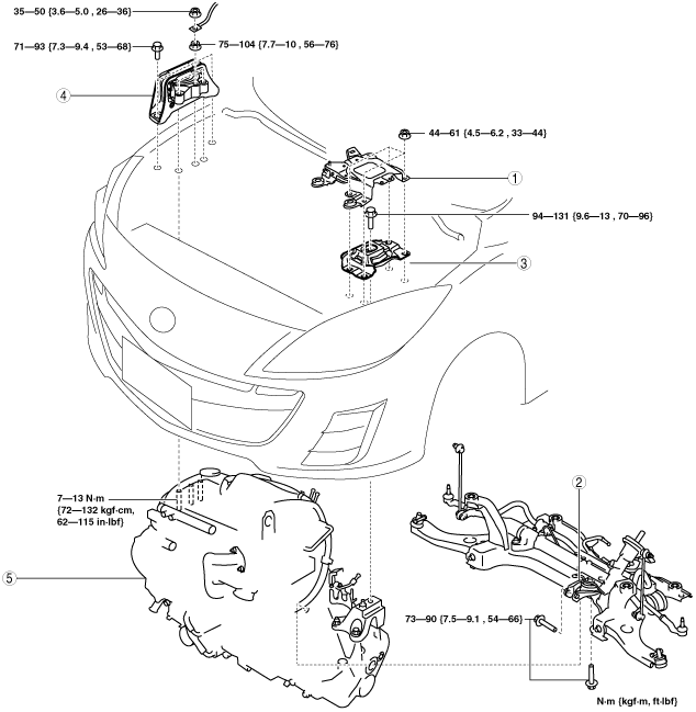
1
|
Battery tray bracket
|
|
2
|
No.1 engine mount rubber, front crossmember component
|
|
3
|
No.4 engine mount rubber
|
|
4
|
No.3 engine mount
|
|
5
|
Engine, transaxle
|
No.1 Engine Mount Rubber, Front Crossmember Component Removal Note
1. Loosen the No.1 engine mount rubber installation bolt (front crossmember side) shown in the figure.
am3zzw00007047
|
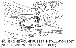
2. Remove the No.1 engine mount rubber installation bolt (No.1 engine mount bracket side) shown in the figure.
am3zzw00007048
|
3. Remove the No.1 engine mount rubber and the front crossmember component as a single unit. (See FRONT CROSSMEMBER REMOVAL/INSTALLATION [MZR-CD 2.2].)
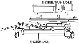
No.3 Engine Mount, No.4 Engine Mount Rubber Removal Note
1. Secure the engine and transaxle using an engine jack.
am3zzw00013064
|
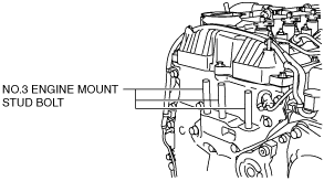
Engine Mount Installation Note
1. Tighten the No.3 engine mount stud bolts.
am3zzw00013065
|
2. Secure the engine and transaxle using an engine jack.
am3zzw00013064
|
3. Temporarily tighten the No.3 engine mount installation bolts and nuts.
am3zzw00009056
|
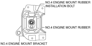
4. Temporarily tighten the No.4 engine mount rubber installation bolt.
am3zzw00013066
|
5. Install the front crossmember component. (See FRONT CROSSMEMBER REMOVAL/INSTALLATION [MZR-CD 2.2].)
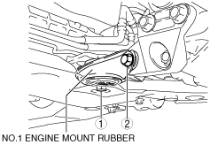
6. Temporarily tighten the No.1 engine mount rubber installation bolts in the order shown in the figure.
am3zzw00013067
|
7. Tighten the No.3 engine mount installation bolts and nuts in the order shown in the figure.
am3zzw00005092
|
8. Tighten the No.4 engine mount rubber installation bolt.
am3zzw00013066
|
9. Tighten the No.1 engine mount rubber installation bolts in the order shown in the figure.
am3zzw00013067
|