DTC P0819:00 [FW6A-EL]


id050225822400

DTC P0819:00

M position switch/Up switch/Down switch signal error

DETECTION CONDITION
•  Under the following conditions, any of (1) to (4) conditions occurs for 1 s:
―  Engine is running.
―  Battery voltage is 8 V or more.
―  Transaxle range sensor related DTC is not recorded.
(1) M position switch signal is on even though forward oil pressure switch is on in any position other than D position.
(2) M position switch signal is off even though up or down switch signal is on in D position.
(3) Up switch signal is on even though M position switch signal is off in any position other than D position.
(4) Down switch signal is on even though M position switch signal is off in any position other than D position.
Diagnostic support note
•  The MIL does not illuminate.
•  The AT warning light does not illuminate.
•  PENDING CODE is available.
•  FREEZE FRAME DATA is not available.
•  The DTC is stored in the TCM memory.
FAIL-SAFE FUNCTION
•  Inhibits manual mode.
POSSIBLE CAUSE
•  Instrument cluster DTC is stored.
•  Selector lever component connector or terminals malfunction
•  Selector lever component malfunction
―  M position switch malfunction
―  Up switch malfunction
―  Down switch malfunction
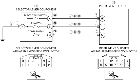
•  Open circuit in wiring harness between selector lever component terminal H and body ground
•  Instrument cluster connector or terminals malfunction
•  Short to ground in wiring harness between the following terminals:
―  Selector lever component terminal A—Instrument cluster terminal 1K
―  Selector lever component terminal B—Instrument cluster terminal 1I
―  Selector lever component terminal C—Instrument cluster terminal 1J
•  Short to power supply in wiring harness between the following terminals:
―  Selector lever component terminal A—Instrument cluster terminal 1K
―  Selector lever component terminal B—Instrument cluster terminal 1I
―  Selector lever component terminal C—Instrument cluster terminal 1J
•  Open circuit in wiring harness between the following terminals:
―  Selector lever component terminal A—Instrument cluster terminal 1K
―  Selector lever component terminal B—Instrument cluster terminal 1I
―  Selector lever component terminal C—Instrument cluster terminal 1J
•  Instrument cluster malfunction

Diagnostic procedure

STEP

INSPECTION

ACTION

1
VERIFY RELATED SERVICE INFORMATION AVAILABILITY
•  Verify related Service Information availability.
•  Is any related Service Information available?
Yes
Perform repair or diagnosis according to the available Service Information.
•  If the vehicle is not repaired, go to the next step.
No
Go to the next step.
2
CONFIRM INSTRUMENT CLUSTER DTC
•  Perform the instrument cluster DTC inspection using the M-MDS.
•  Are any DTCs present?
Yes
Go to the applicable DTC inspection.
No
Go to the next step.
3
INSPECT SELECTOR LEVER COMPONENT CONNECTOR CONDITION
•  Switch the ignition to off.
•  Disconnect the selector lever component connector.
•  Inspect for poor connection (such as damaged/pulled-out pins, corrosion).
•  Is there any malfunction?
Yes
Repair or replace the connector and/or terminals, then go to Step 11.
No
Go to the next step.
4
INSPECT SELECTOR LEVER COMPONENT
•  Inspect the M position switch, up switch and down switch.
•  Is there any malfunction?
Yes
Replace the selector lever component, then go to Step 11.
No
Go to the next step.
5
INSPECT SELECTOR LEVER COMPONENT GROUND CIRCUIT FOR OPEN CIRCUIT
•  Verify that the selector lever component connector is disconnected.
•  Inspect for continuity between selector lever component terminal H (wiring harness-side) and body ground.
•  Is there continuity?
Yes
Go to the next step.
No
Repair or replace the wiring harness for a possible open circuit, then go to Step 11.
6
INSPECT INSTRUMENT CLUSTER CONNECTOR CONDITION
•  Disconnect the instrument cluster connector.
•  Inspect for poor connection (such as damaged/pulled-out pins, corrosion).
•  Is there any malfunction?
Yes
Repair or replace the connector and/or terminals, then go to Step 11.
No
Go to the next step.
7
INSPECT SELECTOR LEVER COMPONENT CIRCUIT FOR SHORT TO GROUND
•  Verify that the selector lever component and instrument cluster connectors are disconnected.
•  Inspect for continuity between the following terminals (wiring harness-side) and body ground:
―  Selector lever component terminal A
―  Selector lever component terminal B
―  Selector lever component terminal C
•  Is there continuity?
Yes
Repair or replace the wiring harness for a possible short to ground, then go to Step 11.
No
Go to the next step.
8
INSPECT SELECTOR LEVER COMPONENT CIRCUIT FOR SHORT TO POWER SUPPLY
•  Verify that the selector lever component and instrument cluster connectors are disconnected.
•  Switch the ignition to ON.
•  Measure the voltage at the following terminals (wiring harness-side):
―  Selector lever component terminal A
―  Selector lever component terminal B
―  Selector lever component terminal C
•  Is there any voltage?
Yes
Repair or replace the wiring harness for a possible short to power supply, then go to Step 11.
No
Go to the next step.
9
INSPECT SELECTOR LEVER COMPONENT CIRCUIT FOR OPEN CIRCUIT
•  Verify that the selector lever component and instrument cluster connectors are disconnected.
•  Switch the ignition to off.
•  Inspect for continuity between the following terminals (wiring harness-side):
―  Selector lever component terminal A—Instrument cluster terminal 1K
―  Selector lever component terminal B—Instrument cluster terminal 1I
―  Selector lever component terminal C—Instrument cluster terminal 1J
•  Is there continuity?
Yes
Go to the next step.
No
Repair or replace the wiring harness for a possible open circuit, then go to Step 11.
10
INSPECT INSTRUMENT CLUSTER
•  Inspect the instrument cluster.
•  Is there any malfunction?
Yes
Replace the instrument cluster, then go to the next step.
No
Go to the next step.
11
VERIFY DTC TROUBLESHOOTING COMPLETED
•  Make sure to reconnect all disconnected connectors.
•  Clear the DTC using the M-MDS.
•  Perform the following procedure to ensure that the DTC has been resolved:
1.  Verify that the battery voltage is 8 V or more.
2.  Drive the vehicle for 1 s or more under the following conditions:
•  Selector lever position: Except D position
3.  Drive the vehicle for 1 s or more under the following conditions:
•  Selector lever position: D position
•  Up switch: On
4.  Drive the vehicle for 1 s or more under the following conditions:
•  Selector lever position: D position
•  Down switch: On
•  Perform the DTC inspection using the M-MDS.
•  Are any DTCs present?
Yes
Go to the applicable DTC inspection.
No
DTC troubleshooting completed.