 |
am6zzw00002069
CLUTCH UNIT REMOVAL/INSTALLATION [G66M-R]
id0510m5800300
1. Disconnect the negative battery cable. (See BATTERY REMOVAL/INSTALLATION [MZR 1.8, MZR 2.0, MZR 2.5].)(See BATTERY REMOVAL/INSTALLATION [MZR 2.0 DISI].)
2. Remove the following parts:
3. Disconnect the A/F sensor connector. (See AIR FUEL RATIO (A/F) SENSOR REMOVAL/INSTALLATION [MZR 1.8, MZR 2.0, MZR 2.5].)(See AIR FUEL RATIO (A/F) SENSOR REMOVAL/INSTALLATION [MZR 2.0 DISI].)
4. Disconnect the HO2S connector. (See HEATED OXYGEN SENSOR (HO2S) REMOVAL/INSTALLATION [MZR 1.8, MZR 2.0, MZR 2.5].)(See HEATED OXYGEN SENSOR (HO2S) REMOVAL/INSTALLATION [MZR 2.0 DISI].)
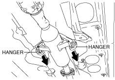
5. Remove the hanger on the TWC side as shown in the figure and set the hanger aside.
am6zzw00002069
|
6. Remove the steering shaft cover. (See STEERING GEAR AND LINKAGE REMOVAL/INSTALLATION [L.H.D.].)(See STEERING GEAR AND LINKAGE REMOVAL/INSTALLATION [R.H.D.].)
7. Remove the joint bolt for the steering shaft and disconnect the steering shaft from the steering gear and linkage side. (See STEERING GEAR AND LINKAGE REMOVAL/INSTALLATION [L.H.D.].)(See STEERING GEAR AND LINKAGE REMOVAL/INSTALLATION [R.H.D.].)
8. Drain the transaxle oil into a suitable container. (See TRANSAXLE OIL REPLACEMENT [G66M-R].)
9. Remove the manual transaxle. (See MANUAL TRANSAXLE REMOVAL/INSTALLATION [G66M-R].)
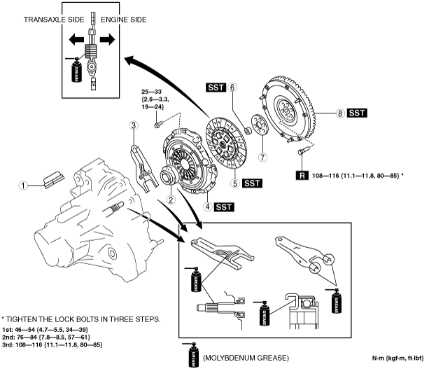
10. Remove in the order indicated in the table.
11. Install in the reverse order of removal.
12. Add the specified amount of specified transaxle oil. (See TRANSAXLE OIL REPLACEMENT [G66M-R].)
MZR 2.0, MZR 2.0 DISI
am6zzw00007078
|
|
1
|
Boot
|
|
2
|
Clutch release collar
|
|
3
|
Clutch release fork
|
|
4
|
Clutch cover
|
|
5
|
Clutch disc
|
|
6
|
Pilot bearing
(See Pilot Bearing Removal Note.)
|
|
7
|
Plate
|
|
8
|
Flywheel
(See Flywheel Removal Note.)
(See Flywheel Installation Note.)
|
MZR 2.5
am6zzw00007079
|
|
1
|
Boot
|
|
2
|
Clutch release collar
|
|
3
|
Clutch release fork
|
|
4
|
Clutch cover
|
|
5
|
Clutch disc
|
|
6
|
Pilot bearing
(See Pilot Bearing Removal Note.)
|
|
7
|
Plate
|
|
8
|
Flywheel
(See Flywheel Removal Note.)
(See Flywheel Installation Note.)
|
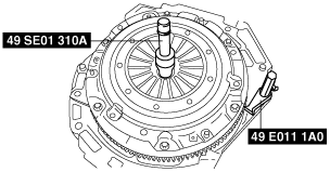
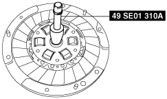
Clutch Cover and Disc Removal Note
1. Install the SSTs.
am6zzw00007080
|
2. Loosen each bolt one turn at a time in a crisscross pattern until spring tension is released.
3. Remove the clutch cover and disc.
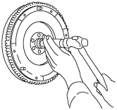
Pilot Bearing Removal Note
1. Use the SST to remove the pilot bearing.
am6zzw00007081
|
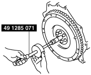
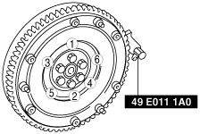
Flywheel Removal Note
1. Hold the flywheel using the SST.
am6zzw00007082
|
2. Loosen the lock bolts uniformly in the order of the numbers shown in the figure and remove the flywheel.
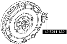
Flywheel Installation Note
1. Clean the crankshaft thread holes.
2. Install the flywheel to the crankshaft.
3. Hand-tighten the new flywheel lock bolts.
4. Install the SST to the flywheel.
am6zzw00007083
|
5. Temporarily tighten the lock bolts uniformly in the order of the numbers shown in the figure and install the flywheel.
6. Tighten the lock bolts in three steps in the order shown in the figure.
Pilot Bearing Installation Note
1. Install the pilot bearing using the corresponding 20 mm {0.79 in} side of a Snap-on brand millimeter size bushing driver set A160M adapter A160M7 (20—22 mm {0.79—0.86 in}) or substitution tool.
am6zzw00007084
|
2. Press-fit the pilot bearing to the position which is 4.0—5.0 mm {0.16—0.19 in} from the crankshaft end.
am6zzw00007085
|
Clutch Disc Installation Note
1. Clean the splines of the clutch disc and the main drive gear with a brush.
2. Spread a thin layer of clutch grease on the splines.
3. Hold the clutch disc position using the SST.
am6zzw00007086
|
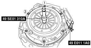
Clutch Cover Installation Note
1. Install the SSTs.
am6zzw00007087
|
2. Tighten the bolts uniformly in the order of the numbers shown in the figure and install the clutch cover.