 |
am6zzw00002070
MANUAL TRANSAXLE REMOVAL/INSTALLATION [G66M-R]
id0515k1800600
1. Disconnect the negative battery cable. (See BATTERY REMOVAL/INSTALLATION [MZR 1.8, MZR 2.0, MZR 2.5].)(See BATTERY REMOVAL/INSTALLATION [MZR 2.0 DISI].)
2. Remove the following parts:
3. Disconnect the A/F sensor connector. (See AIR FUEL RATIO (A/F) SENSOR REMOVAL/INSTALLATION [MZR 1.8, MZR 2.0, MZR 2.5].)(See AIR FUEL RATIO (A/F) SENSOR REMOVAL/INSTALLATION [MZR 2.0 DISI].)
4. Disconnect the HO2S connector. (See HEATED OXYGEN SENSOR (HO2S) REMOVAL/INSTALLATION [MZR 1.8, MZR 2.0, MZR 2.5].)(See HEATED OXYGEN SENSOR (HO2S) REMOVAL/INSTALLATION [MZR 2.0 DISI].)
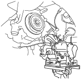
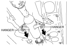
5. Remove the hanger on the TWC side as shown in the figure and set the hanger aside.
am6zzw00002070
|
6. Remove the steering shaft cover. (See STEERING GEAR AND LINKAGE REMOVAL/INSTALLATION [L.H.D.].)(See STEERING GEAR AND LINKAGE REMOVAL/INSTALLATION [R.H.D.].)
7. Remove the joint bolt for the steering shaft and disconnect the steering shaft from the steering gear and linkage side. (See STEERING GEAR AND LINKAGE REMOVAL/INSTALLATION [L.H.D.].)(See STEERING GEAR AND LINKAGE REMOVAL/INSTALLATION [R.H.D.].)
8. Drain the transaxle oil into a suitable container. (See TRANSAXLE OIL REPLACEMENT [G66M-R].)
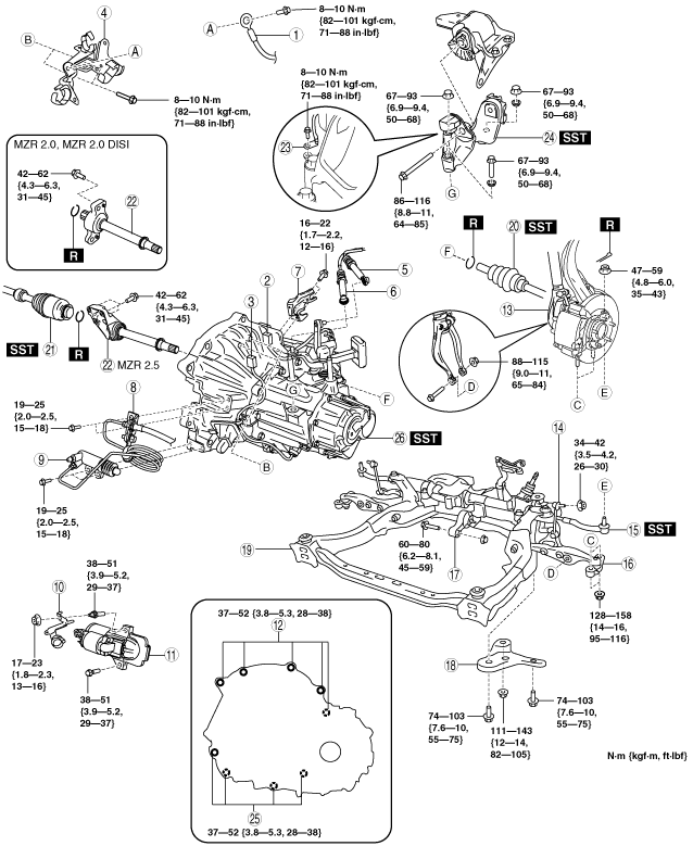
9. Remove in the order indicated in the table.
10. Install in the reverse order of removal.
11. Add the specified amount of specified transaxle oil. (See TRANSAXLE OIL REPLACEMENT [G66M-R].)
am6zzw00006174
|
|
1
|
GND wiring harness
|
|
2
|
Back-up light switch connector
|
|
3
|
Neutral switch connector
|
|
4
|
Harness bracket
|
|
5
|
Selector cable
|
|
6
|
Shift cable
|
|
7
|
Cable bracket
|
|
8
|
Clutch release cylinder bracket
|
|
9
|
Clutch release cylinder
|
|
10
|
Heater hose bracket
|
|
11
|
Starter
|
|
12
|
Transaxle mounting bolt (upper side)
|
|
13
|
Damper fork
|
|
14
|
Stabilizer control link
|
|
15
|
Tie-rod end ball joint
|
|
16
|
Lower arm ball joint
|
|
17
|
No.1 engine mount
|
|
18
|
Crossmember bracket
|
|
19
|
Crossmember component
|
|
20
|
Drive shaft (LH)
|
|
21
|
Drive shaft (RH)
|
|
22
|
Joint shaft
|
|
23
|
GND wiring harness
|
|
24
|
No.4 engine mount bracket
|
|
25
|
Transaxle mounting bolt (lower side)
|
|
26
|
Manual transaxle
|
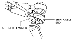
Shift Cable and Selector Cable Removal Note
1. Remove the both shift cable end and selector cable end using a fastener remover.
am6zzw00006175
|
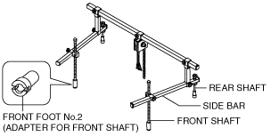
No.4 Engine Mount Removal Note
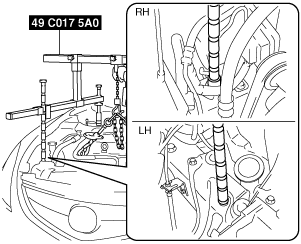
1. Install the SST using the following procedure.
am6zzw00006176
|
am6zzw00006177
|
am6zzw00006178
|
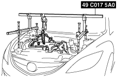
2. Support the engine using the SST.
am6zzw00006179
|
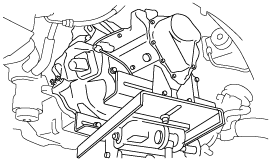
3. Remove the No.4 engine mount rubber and bracket.
Manual Transaxle Removal Note
1. Adjust the SST and lean the engine toward the transaxle.
am6zzw00006179
|
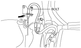
2. Remove the bolt securing the brake hose to the bracket as shown in the figure, and disconnect brake hose from the bracket.
am6zzw00006180
|
3. Support the transaxle on a jack.
am6zzw00006181
|
4. Remove the transaxle mounting bolts.
5. Remove the transaxle.
Manual Transaxle Installation Note
1. Set the transaxle on a jack and lift into place.
am6zzw00006182
|
2. Install the transaxle mounting bolts.
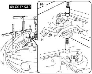
3. Adjust the SST (49 C017 5A0) so that the engine is located at the specified position.
4. Install the brake hose to the bracket and tighten the bolt shown in the figure.
am6zzw00006183
|
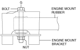
No.1 Engine Mount and No.4 Engine Mount Installation Note
1. Install the No.1 engine mount bracket to the No.1 engine mount rubber as shown in the figure.
am6zzw00007303
|
2. Temporarily tighten the bolt G.
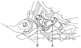
3. Install the No.1 engine mount bracket to the transaxle and temporarily tighten bolts A and B.
am6zzw00006185
|
4. Tighten the bolts in the order of A and B.
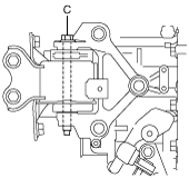
5. Align the stud bolts to their installation holes and install the No.4 engine mount bracket to the transaxle.
6. Align the No.4 engine mount bracket installation hole to the No.4 engine mount rubber on the body and temporarily tighten bolt C.
am6zzw00006186
|
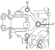
7. Temporarily tighten bolt D, and then the nuts in the order of E and F.
am6zzw00006187
|
8. Tighten bolt D, and then the nuts in the order of E and F.
9. Tighten the bolt C.
10. Tighten the bolt G.
am6zzw00007304
|
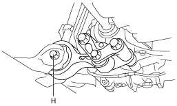
11. Tighten the bolt H.
am6zzw00006188
|