DTC B1423:11, B1423:13, B1423:87, B1423:96 [SAS CONTROL MODULE (ACTIVE BONNET)]


id0802h4008300

System malfunction location

•  B1423:11: Active bonnet sensor (left, right or left, left or right, center) circuit short to body ground ground
•  B1423:13: Active bonnet sensor (right, center) circuit open circuit or resistance high or short to power supply
•  B1423:87: Signal reception error from active bonnet sensor (right, center)
•  B1423:96: Active bonnet sensor (right, center) internal malfunction
Detection condition
Warning
•  Detection conditions are for understanding the DTC outline before performing an inspection. Performing an inspection according to only the detection conditions may cause injury due to an operating error, or damage the system. When performing an inspection, always follow the inspection procedure.
•  Wiring harness between the active bonnet sensor (left, right or left, left or right, center) and SAS control module has a malfunction
•  Active bonnet sensor (right, center) has a malfunction
Fail-safe
Not applicable
Possible cause
•  Active bonnet sensor (left, right or left, left or right, center) connector malfunction
•  Active bonnet sensor (right, center) malfunction
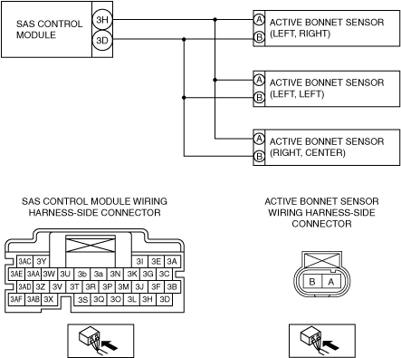
•  Open circuit in the wiring harness between the following terminals:
―  SAS control module terminal 3H—active bonnet sensor (right, center) terminal A
―  SAS control module terminal 3D—active bonnet sensor (right, center) terminal B
•  Short circuit to body ground in the wiring harness between the following terminals:
―  SAS control module terminal 3H—active bonnet sensor (left, right) terminal A
―  SAS control module terminal 3D—active bonnet sensor (left, right) terminal B
―  SAS control module terminal 3H—active bonnet sensor (left, left) terminal A
―  SAS control module terminal 3D—active bonnet sensor (left, left) terminal B
―  SAS control module terminal 3H—active bonnet sensor (right, center) terminal A
―  SAS control module terminal 3D—active bonnet sensor (right, center) terminal B
•  Short circuit to power supply in the wiring harness between the following terminals:
―  SAS control module terminal 3H—active bonnet sensor (left, right) terminal A
―  SAS control module terminal 3D—active bonnet sensor (left, right) terminal B
―  SAS control module terminal 3H—active bonnet sensor (left, left) terminal A
―  SAS control module terminal 3D—active bonnet sensor (left, left) terminal B
―  SAS control module terminal 3H—active bonnet sensor (right, center) terminal A
―  SAS control module terminal 3D—active bonnet sensor (right, center) terminal B
•  SAS control module malfunction


Diagnostic Procedure

Step

Inspection

Action

1
INSPECT ACTIVE BONNET SENSOR (RIGHT, CENTER) CONNECTOR
Warning
•  Handling the component parts improperly can accidentally operate (deploy) the air bag module, which may seriously injure you. Read the service warnings/cautions and the workshop manual before handling the air bag system components.
•  Switch the ignition off.
•  Disconnect the negative battery terminal and wait for 1 min or more. (See NEGATIVE BATTERY TERMINAL DISCONNECTION/CONNECTION.)
•  Remove the front bumper. (See FRONT BUMPER REMOVAL/INSTALLATION.)
•  Disconnect the active bonnet sensor (right, center) connector. (See ACTIVE BONNET SENSOR REMOVAL/INSTALLATION.)
•  Inspect the active bonnet sensor (right, center) connector (wiring harness-side). (Corrosion, damage, and disconnected pins)
•  Is there any malfunction of the active bonnet sensor (right, center) connector (wiring harness-side)?
Yes
Replace the malfunctioning part, then go to Step 5.
No
Go to the next step.
2
INSPECT ACTIVE BONNET SENSOR (LEFT, RIGHT), (LEFT, LEFT), (RIGHT, CENTER) CIRCUIT FOR SHORT TO GROUND
•  Remove the column cover. (See COLUMN COVER REMOVAL/INSTALLATION.)
•  Disconnect the clock spring connector. (See CLOCK SPRING REMOVAL/INSTALLATION [TWO-STEP DEPLOYMENT CONTROL SYSTEM].)
•  Remove the glove compartment. (See GLOVE COMPARTMENT REMOVAL/INSTALLATION.)
•  Disconnect the passenger-side air bag module connector. (See PASSENGER-SIDE AIR BAG MODULE REMOVAL/INSTALLATION [TWO-STEP DEPLOYMENT CONTROL SYSTEM].)
•  Disconnect the driver and passenger-side front seat connectors. (See FRONT SEAT REMOVAL/INSTALLATION.)
•  Remove the headliner. (See HEADLINER REMOVAL/INSTALLATION.)
•  Disconnect the driver and passenger-side curtain air bag module connectors. (See CURTAIN AIR BAG MODULE REMOVAL/INSTALLATION [TWO-STEP DEPLOYMENT CONTROL SYSTEM].)
•  Remove the B-pillar lower trim. (See B-PILLAR LOWER TRIM REMOVAL/INSTALLATION.)
•  Disconnect the driver and passenger-side pre-tensioner seat belt connectors. (See FRONT SEAT BELT REMOVAL/INSTALLATION.)
•  Remove the rear console. (See REAR CONSOLE REMOVAL/INSTALLATION.)
•  Disconnect the passenger-side pressure sensor connector. (See PRESSURE SENSOR REMOVAL/INSTALLATION [TWO-STEP DEPLOYMENT CONTROL SYSTEM].)
•  Disconnect the active bonnet actuator connector.
•  Disconnect the all SAS control module connectors. (See SAS CONTROL MODULE REMOVAL/INSTALLATION [TWO-STEP DEPLOYMENT CONTROL SYSTEM].)
•  Inspect for continuity between the following terminals (wiring harness-side) and body ground:
―  SAS control module terminal 3H
―  SAS control module terminal 3D
Note
•  Inspect for continuity while shaking the wiring harness between the SAS control module and active bonnet sensor (left, right), (left, left), (right, center).
•  Is there continuity?
Yes
Refer to the wiring diagram and verify whether or not there is a common connector between SAS control module terminal and active bonnet sensor (left, right), (left, left), (right, center) terminal.
If there is a common connector:
•  Determine the malfunctioning part by inspecting the common connector and the terminal for corrosion, damage, or pin disconnection, and the common wiring harness for a short to ground.
•  Replace the malfunctioning part.
If there is no common connector:
•  Replace the wiring harness which has a short to ground.
Go to Step 5.
No
Go to the next step.
3
INSPECT ACTIVE BONNET SENSOR (RIGHT, CENTER) CIRCUIT FOR OPEN CIRCUIT
•  Active bonnet sensor (right, center) and SAS control module connectors are disconnected.
•  Inspect for continuity between the following terminals (wiring harness-side):
―  Active bonnet sensor (right, center) terminal A—SAS control module terminal 3H
―  Active bonnet sensor (right, center) terminal B—SAS control module terminal 3D
Note
•  Inspect for continuity while shaking the wiring harness between the SAS control module and active bonnet sensor (right, center).
•  Is there continuity?
Yes
Go to the next step.
No
Refer to the wiring diagram and verify whether or not there is a common connector between SAS control module terminal and active bonnet sensor (right, center) terminal.
If there is a common connector:
•  Determine the malfunctioning part by inspecting the common connector and the terminal for corrosion, damage, or pin disconnection, and the common wiring harness for an open circuit.
•  Replace the malfunctioning part.
If there is no common connector:
•  Replace the wiring harness which has an open circuit.
Go to Step 5.
4
INSPECT ACTIVE BONNET SENSOR (LEFT, RIGHT), (LEFT, LEFT), (RIGHT, CENTER) CIRCUIT FOR SHORT TO POWER SUPPLY
•  Active bonnet sensor (left, right), (left, left), (right, center) and SAS control module connectors are disconnected.
•  Connect the negative battery terminal. (See NEGATIVE BATTERY TERMINAL DISCONNECTION/CONNECTION.)
•  Switch the ignition ON (engine off or on).
•  Measure the voltage at the following terminals (wiring harness-side):
―  SAS control module terminal 3H
―  SAS control module terminal 3D
Note
•  Measure the voltage while shaking the wiring harness between the SAS control module and active bonnet sensor (left, right), (left, left), (right, center).
•  Is the voltage 0 V?
Yes
Replace the active bonnet sensor (left, right), (left, left), (right, center) then go to the next step. (See ACTIVE BONNET SENSOR REMOVAL/INSTALLATION.)
No
Refer to the wiring diagram and verify whether or not there is a common connector between SAS control module terminal and active bonnet sensor (left, right), (left, left), (right, center) terminal.
If there is a common connector:
•  Determine the malfunctioning part by inspecting the common connector and the terminal for corrosion, damage, or pin disconnection, and the common wiring harness for a short to power supply.
•  Replace the malfunctioning part.
If there is no common connector:
•  Replace the wiring harness which has a short to power supply.
Go to the next step.
5
PERFORM SAS CONTROL MODULE DTC INSPECTION
•  Switch the ignition off.
•  Disconnect the negative battery terminal and wait for 1 min or more.
•  Connect the SAS control module connectors.
•  Reconnect all disconnected connectors.
•  Connect the negative battery terminal. (See NEGATIVE BATTERY TERMINAL DISCONNECTION/CONNECTION.)
•  Switch the ignition ON (engine off or on).
•  Clear the DTC for the SAS control module using the M-MDS.
•  Perform the DTC inspection for the SAS control module using the M-MDS.
•  Are the same Pending DTCs present?
Yes
Repeat the inspection from Step 1.
•  If the malfunction recurs, replace the SAS control module.
No
DTC troubleshooting completed.