ENGINE REMOVAL/INSTALLATION [L8, LF, L5]
id0110a6800400
-
Warning
-
• Fuel vapor is hazardous. It can very easily ignite, causing serious injury and damage. Always keep sparks and flames away from fuel.
• Fuel line spills and leakage are dangerous. Fuel can ignite and cause serious injuries or death and damage. Fuel can also irritate skin and eyes. To prevent this, always complete the “Fuel Line Safety Procedure”. (See
BEFORE SERVICE PRECAUTION [L8, LF, L5].)
-
Caution
-
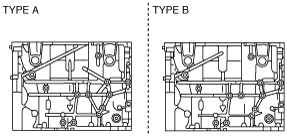
L5
• If the crankshaft and the cylinder block are replaced with a type B from a type A as shown in the figure, perform PCM reprogramming. Otherwise, the engine could be damaged. (See
PCM REPROGRAMMING [L8, LF, L5].)
Crankshaft
Cylinder block
-
Note
-
• Perform the engine and transaxle component removal/installation from below the vehicle.
1. Remove the battery and battery tray. (See BATTERY REMOVAL/INSTALLATION [L8, LF, L5].)
2. Remove the plug hole plate. (See PLUG HOLE PLATE REMOVAL/INSTALLATION [L8, LF, L5].)
3. Remove the air hose and air cleaner component. (See INTAKE-AIR SYSTEM REMOVAL/INSTALLATION [L8, LF, L5].)
4. Set the cooler pipe and the cooler hose (LO) out of the way. (See REFRIGERANT LINE REMOVAL/INSTALLATION.)
5. Disconnect the brake vacuum hose. (See VACUUM HOSE REMOVAL/INSTALLATION [EXCEPT MZR-CD (RF Turbo), MZR-CD 2.2].)
6. Remove the front wheels and tires (See GENERAL PROCEDURES (SUSPENSION).)
7. Set the front mudguards out of the way. (See FRONT MUDGUARD REMOVAL/INSTALLATION.)
8. Remove the splash shields.
9. Remove the aerodynamic under cover No.1 and No.2. (See AERODYNAMIC UNDER COVER NO.1 REMOVAL/INSTALLATION.) (See AERODYNAMIC UNDER COVER NO.2 REMOVAL/INSTALLATION.)
10. Remove the drive belt. (See DRIVE BELT REMOVAL/INSTALLATION [L8, LF, L5].)
11. Remove the tunnel member. (L8, LF) (See EXHAUST SYSTEM REMOVAL/INSTALLATION [L8, LF, L5].)
12. Remove the TWC. (See EXHAUST SYSTEM REMOVAL/INSTALLATION [L8, LF, L5].)
13. Drain the engine coolant. (See ENGINE COOLANT REPLACEMENT [L8, LF, L5].)
14. Drain the ATF (ATX) or transaxle oil (MTX). (See AUTOMATIC TRANSAXLE FLUID (ATF) REPLACEMENT [FS5A-EL] (ATX).) (See TRANSAXLE OIL REPLACEMENT [G35M-R] (5MTX).) (See TRANSAXLE OIL REPLACEMENT [G66M-R] (6MTX).)
15. Disconnect the drive shafts from the engine side, set the drive shafts out of the way. (See DRIVE SHAFT REMOVAL/INSTALLATION.)
16. Disconnect the radiator hose. (See RADIATOR REMOVAL/INSTALLATION [L8, LF, L5].)
17. Disconnect the vacuum hose and the heater hose.
18. Disconnect the oil hose, selector cable, and wiring harness. (ATX) (See AUTOMATIC TRANSAXLE REMOVAL/INSTALLATION [FS5A-EL].)
19. Disconnect the shift cable and selector cable. (MTX) (See MANUAL TRANSAXLE REMOVAL/INSTALLATION [G35M-R] (5MTX).) (See MANUAL TRANSAXLE REMOVAL/INSTALLATION [G66M-R] (6MTX).)
20. Remove the clutch release cylinder with the pipe still connected. (MTX) (See CLUTCH RELEASE CYLINDER REMOVAL/INSTALLATION [L8, LF, L5, MZR-CD (RF Turbo)].)
21. Disconnect the fuel hose. (See FUEL INJECTOR REMOVAL/INSTALLATION [L8, LF, L5].)
22. Remove the A/C compressor with the pipes still connected. (See A/C COMPRESSOR REMOVAL/INSTALLATION.)
23. Disconnect the wiring harness from the engine side.
24. Remove in the order indicated in the table.
25. Install in the reverse order of removal.
26. Start the engine. And inspect and adjust the following:
-
• Leakage of engine oil, engine coolant, ATF, transaxle oil, and fuel.
• Runout and contact of pulley and belt.
• Engine-driven accessories operation.
-
Note
-
• If the engine is overhauled and installed to the vehicle, perform the road test and verify that there is no abnormality.
|
1
|
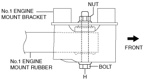
No.1 engine mount
|
|
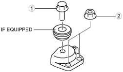
2
|
No.4 Engine mount bracket
|
|
3
|
No.3 Engine mount bracket
|
|
4
|
Engine, transaxle
|
No.1 Engine Mount Removal Note
-
Note
-
No.3 Engine Mount Bracket, No.4 Engine Bracket Removal Note
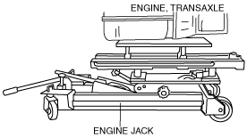
1. Secure the engine and transaxle using an engine jack.
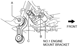
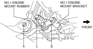
Engine Mount Installation Note
1. Install the through bolt A on the front crossmember side until approximately three pitches are showing.
2. Temporarily tighten bolts B and C.
-
Note
-
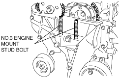
• If the No.3 engine mount bracket and the engine are removed, retighten the No.3 engine mount stud bolts.
3. Tighten the No. 3 engine mount stud bolts.
-
Tightening torque
-
7—13 N·m {72—132 kgf·cm, 62—115 in·lbf}
4. Secure the engine and transaxle using an engine jack.
5. Temporarily tighten the No.3 engine mount nuts.
6. Tighten the No.3 engine mount nuts in the order shown in the figure.
-
Tightening torque
-
75—104 N·m {7.6—10 kgf·m, 55—77 ft·lbf}
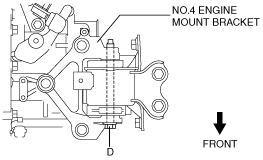
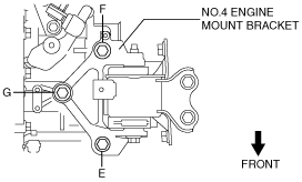
7. Align the No.4 engine mount bracket installation hole to the No.4 engine mount rubber on the body and temporarily tighten bolt D.
8. Temporarily tighten bolt E, and then the nuts in the order of F, G.
9. Tighten bolt E, and then the nuts in the order of F, G.
-
Tightening torque
-
67—93 N·m {6.9—9.4 kgf·m, 50—68 ft·lbf}
10. Tighten the bolt D.
-
Tightening torque
-
86—116 N·m {8.8—11 kgf·m, 64—85 ft·lbf}
11. Tighten the bolt H.
-
Tightening torque
-
60—80 N·m {6.1—8.2 kgf·m, 44—59 ft·lbf}
12. Tighten the bolts in the order of B and C.
-
Tightening torque
-
94—116 N·m {9.6—11 kgf·m, 70—85 ft·lbf}
13. Tighten the bolt A.
-
Tightening torque
-
94—116 N·m {9.6—11 kgf·m, 70—85 ft·lbf}