 |
am6zzw00002736
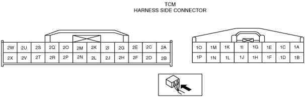
TCM INSPECTION [FS5A-EL]
id051721800300
1. Measure the voltage at each terminal.
Terminal Voltage Table (Reference)
am6zzw00002736
|
|
Terminal |
Signal |
Connected to |
Test condition |
Voltage (V) |
Action |
|
|---|---|---|---|---|---|---|
|
1A
|
Shift solenoid A control
|
Shift solenoid A
|
• Inspect using the wave profile.
|
• Inspect shift solenoid A
• Inspect related harness
|
||
|
1B
|
Shift solenoid B control
|
Shift solenoid B
|
• Inspect using the wave profile.
|
• Inspect shift solenoid B
• Inspect related harness
|
||
|
1C
|
Shift solenoid C control
|
Shift solenoid C
|
• Inspect using the wave profile.
|
• Inspect shift solenoid C
• Inspect related harness
|
||
|
1D
|
Pressure control solenoid B
|
Pressure control solenoid B
|
• Inspect using the wave profile.
|
• Inspect pressure control solenoid B
• Inspect related harness
|
||
|
1E
|
Pressure control solenoid A (+)
|
Pressure control solenoid A
|
• Inspect using the wave profile.
|
• Inspect pressure control solenoid A
• Inspect related harness
|
||
|
1F
|
Shift solenoid D control
|
Shift solenoid D
|
Selector lever is at P, N, D (2GR, 4GR, 5GR), M (1GR) position
|
B+
|
• Inspect shift solenoid D
• Inspect related harness
|
|
|
Other
|
Below 1.0
|
|||||
|
1G
|
Pressure control solenoid A (–)
|
Pressure control solenoid A
|
• Inspect using the wave profile.
|
• Inspect pressure control solenoid A
• Inspect related harness
|
||
|
1H
|
Shift solenoid E control
|
Shift solenoid E
|
Detects TCC operating
|
B+
|
• Inspect shift solenoid E
• Inspect related harness
|
|
|
Other
|
Below 1.0
|
|||||
|
1I
|
—
|
—
|
—
|
—
|
—
|
|
|
1J
|
Shift solenoid F control
|
Shift solenoid F
|
1GR, 2GR, 3GR, 4GR
|
B+
|
• Inspect shift solenoid F
• Inspect related harness
|
|
|
5GR
|
Below 1.0
|
|||||
|
1K
|
Back-up power supply
|
Battery (positive terminal)
|
Under any condition
|
B+
|
• Inspect battery
• Inspect related harness
|
|
|
1L
|
Vehicle speed output
|
BCM
|
• Inspect using the wave profile.
|
• Inspect VSS
• Inspect related harness
|
||
|
1M
|
B+
|
AT Main relay
|
Switch the ignition to off
|
Below 1.0
|
• Inspect AT Main relay
(See RELAY INSPECTION.)
• Inspect related harness
|
|
|
Switch the ignition to ON
|
B+
|
|||||
|
1N
|
B+
|
AT Main relay
|
Switch the ignition to off
|
Below 1.0
|
• Inspect AT Main relay
(See RELAY INSPECTION.)
• Inspect related harness
|
|
|
Switch the ignition to ON
|
B+
|
|||||
|
1O
|
GND
|
Body GND
|
Under any condition
|
Below 1.0
|
• Inspect related harness
|
|
|
1P
|
GND
|
Body GND
|
Under any condition
|
Below 1.0
|
• Inspect related harness
|
|
|
2A
|
—
|
—
|
—
|
—
|
—
|
|
|
2B
|
M range
|
M range switch
|
Switch the ignition to ON
|
M range position
|
Below 1.0
|
• Inspect M range switch
• Inspect related harness
|
|
Other
|
B+
|
|||||
|
2C
|
—
|
—
|
—
|
—
|
—
|
|
|
2D
|
Manual up
|
Up switch
|
Switch the ignition to ON
|
Detects up-shift operation of selector lever in M range
|
Below 1.0
|
• Inspect up switch
• Inspect related harness
|
|
Other
|
B+
|
|||||
|
2E
|
—
|
—
|
—
|
—
|
—
|
|
|
2F
|
Manual down
|
Down switch
|
Switch the ignition to ON
|
Detects down-shift operation of selector lever in M range
|
Below 1.0
|
• Inspect down switch
• Inspect related harness
|
|
Other
|
B+
|
|||||
|
2G
|
—
|
—
|
—
|
—
|
—
|
|
|
2H
|
Selector lever position
|
TR switch
(terminal C)
|
Switch the ignition to ON
|
P position
|
Approx. 4.6
|
• Inspect TR switch
• Inspect related harness
|
|
R position
|
Approx. 3.9
|
|||||
|
N position
|
Approx. 3.2
|
|||||
|
D range
M range
|
Approx. 2.5
|
|||||
|
2I
|
Input/turbine speed sensor (+)
|
Input/turbine speed sensor
|
• Inspect using the wave profile.
|
• Inspect input/turbine speed sensor
• Inspect related harness
|
||
|
2J
|
Oil pressure
|
Oil pressure switch
|
Switch the ignition to ON
|
Detects forward clutch pressure
|
Below 1.0
|
• Inspect oil pressure switch
• Inspect related harness
|
|
Other
|
B+
|
|||||
|
2K
|
Input/turbine speed sensor (–)
|
Input/turbine speed sensor
|
• Inspect using the wave profile.
|
• Inspect input/turbine speed sensor
• Inspect related harness
|
||
|
2L
|
Secondary gear rotating speed
|
Intermediate sensor
|
• Inspect using the wave profile.
|
• Inspect intermediate sensor
• Inspect related harness
|
||
|
2M
|
ATF temperature
|
TFT sensor
|
Switch the ignition to ON
|
TFT 20 °C
{68 °F}
|
Approx. 3.3
|
• Inspect TFT sensor
• Inspect related harness
|
|
TFT 40 °C
{104 °F}
|
Approx. 2.4
|
|||||
|
TFT 60 °C
{140 °F}
|
Approx. 1.5
|
|||||
|
2N
|
Sensor GND
|
Steering shift switch
|
Under any condition
|
Below 1.0
|
• Inspect related harness
|
|
|
2O
|
Sensor GND
|
TFT sensor, TR switch
|
Under any condition
|
Below 1.0
|
• Inspect related harness
|
|
|
2P
|
Vehicle speed
|
VSS
|
• Inspect using the wave profile.
|
• Inspect VSS
• Inspect related harness
|
||
|
2Q
|
Up-shift or down-shift request
|
Steering shift switch
|
Switch the ignition to ON
|
Up switch and down switch released
|
Approx. 5.0
|
• Inspect steering shift switch
• Inspect related harness
|
|
Down switch depressed
|
Approx. 2.8
|
|||||
|
Up switch depressed
|
Approx. 2.2
|
|||||
|
2R
|
AT Main relay control
|
AT Main relay
|
Switch the ignition to off
|
B+
|
• Inspect AT main relay
(See RELAY INSPECTION.)
• Inspect related harness
|
|
|
Switch the ignition to ON
|
Below 1.0
|
|||||
|
2S
|
—
|
—
|
—
|
—
|
—
|
|
|
2T
|
—
|
—
|
—
|
—
|
—
|
|
|
2U
|
—
|
—
|
—
|
—
|
—
|
|
|
2V
|
—
|
—
|
—
|
—
|
—
|
|
|
2W
|
CAN_H
|
Other modules
|
Because this terminal is for CAN, adequate determination by terminal voltage is not possible.
|
—
|
||
|
2X
|
CAN_L
|
Other modules
|
Because this terminal is for CAN, adequate determination by terminal voltage is not possible.
|
—
|
||
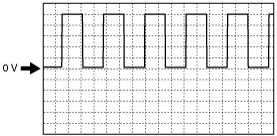
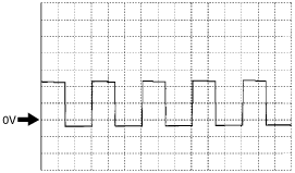
Inspection Using an Oscilloscope (Reference)
Secondary gear rotating speed signal
am6zzw00002737
|
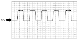
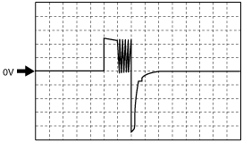
VSS signal (input)
am6zzw00002737
|
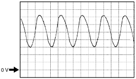
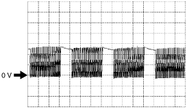
Vehicle speed signal (output)
b6e413zwc002
|
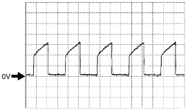
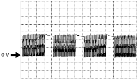
Input/turbine speed sensor signal
am6zzw00002738
|
Pressure control solenoid A signal
(–)
am6zzw00002739
|
(+)
am6zzw00002740
|
Pressure control solenoid B signal
am6zzw00002943
|
Shift solenoid A control
am6zzw00002742
|
Shift solenoid B control
am6zzw00002743
|
Shift solenoid C control
am6zzw00002744
|