 |
ar8wzw00000873
INTAKE MANIFOLD REMOVAL/INSTALLATION [13B-MSP]
id0113z3802000
1. Complete the “BEFORE SERVICE PRECAUTION”. (See BEFORE SERVICE PRECAUTION [13B-MSP].)
2. Remove the following parts:
3. Drain the engine coolant. (SeeENGINE COOLANT REPLACEMENT [13B-MSP].)
4. Disconnect the brake vacuum hose. (See POWER BRAKE UNIT REMOVAL/INSTALLATION.)
5. Disconnect the fuel hose from the fuel distributor (housing side). (See FUEL INJECTOR REMOVAL/INSTALLATION [13B-MSP].)
6. Remove the A/C belt. (See DRIVE BELT REPLACEMENT [13B-MSP].)
7. Remove the A/C compressor with the pipes connected and secure the A/C compressor using wire or rope so that it is out of the way.
8. Disconnect the engine wiring harness from the main fuse block side.
9. Remove the aerodynamic under cover. (See AERODYNAMIC UNDER COVER REMOVAL/INSTALLATION.)
10. Remove the under cover. (See ENGINE OIL REPLACEMENT [13B-MSP].)
11. Disconnect front ABS wheel speed sensor connector. (See FRONT ABS WHEEL-SPEED SENSOR REMOVAL/INSTALLATION.)
12. Remove the clutch release cylinder with the pipes connected and secure the clutch release cylinder using wire or rope so that it is out of the way. (MT) (See CLUTCH RELEASE CYLINDER REMOVAL/INSTALLATION.)
13. Remove the shift lever component. (MT) (See TRANSMISSION REMOVAL/INSTALLATION [P66M-D].)
14. Disconnect the radiator hose, the heater hose and coolant reserve tank hose.
15. Disconnect the selector link. (AT) (See AUTOMATIC TRANSMISSION REMOVAL/INSTALLATION [SJ6A-EL].)
16. Remove the engine, transmission, and crossmember component. (See ENGINE REMOVAL/INSTALLATION [13B-MSP].)
17. Remove the extension manifold (upper and lower). (See INTAKE-AIR SYSTEM REMOVAL/INSTALLATION [13B-MSP].)
18. Remove the AIR control valve. (See SECONDARY AIR INJECTION (AIR) CONTROL VALVE REMOVAL/INSTALLATION [13B-MSP].)
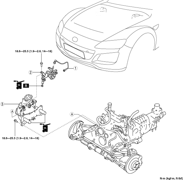
19. Remove in the order indicated in the table.
20. Install in the reverse order of removal.
ar8wzw00000873
|
|
1
|
Fuel hose
|
|
2
|
Fuel distributor (intake manifold side)
|
|
3
|
Intake manifold
|
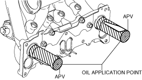
Intake Manifold Installation Note
1. Apply oil thoroughly to the APV as shown in the figure.
ar8uuw00001316
|
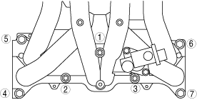
2. Tighten the bolts in the order shown in the figure
ar8uuw00001317
|
3. Retighten the No.1 bolt after tighten the all bolts.