BRAKE PEDAL REMOVAL/INSTALLATION [L.H.D.]
id041100700550
Replacement Part
|
Brake switch
Quantity: 1
Location of use: Brake pedal
|
-
Warning
-
• If the initialization of the sensors for the electronically controlled brake unit related parts is not completed, the electronically controlled brake unit will not operate normally which could lead to an unexpected accident. Therefore, if the electronically controlled brake unit is replaced and removed/installed, always perform the initialization of the sensors for the electronically controlled brake unit related parts so that the electronically controlled brake unit will operate normally.
-
Caution
-
• The clearance between the brake switch and the brake pedal is automatically adjusted to the correct amount when the brake switch is inserted into the installation hole on the brake pedal and rotated to fix in place. If the brake switch is not properly installed, the clearance may be incorrect, causing a brake light malfunction. Therefore, always verify that the brake pedal is properly installed and fully released before installing the brake switch to the pedal.
• Once the brake switch clearance has automatically been adjusted, it cannot be adjusted again. Therefore, replace the switch with a new one when replacing the electronically controlled brake unit or the pedal, or performing any procedure that changes the pedal stroke.
1. Disconnect the negative lead-acid battery terminal. (See NEGATIVE LEAD-ACID BATTERY TERMINAL DISCONNECTION/CONNECTION.)
2. Remove the following parts.
- (1) Selector lever knob. (See SELECTOR LEVER REMOVAL/INSTALLATION [A71M].)
-
- (2) Shift panel (See SHIFT PANEL REMOVAL/INSTALLATION.)
-
- (3) Console panel (See CONSOLE PANEL REMOVAL/INSTALLATION.)
-
- (4) Rear console (See REAR CONSOLE REMOVAL/INSTALLATION.)
-
- (5) Console bracket (See CONSOLE BRACKET REMOVAL/INSTALLATION.)
-
- (6) Front console upper panel (See FRONT CONSOLE UPPER PANEL REMOVAL/INSTALLATION.)
-
- (7) Console side panel (See CONSOLE SIDE PANEL REMOVAL/INSTALLATION.)
-
- (8) Front console box (See FRONT CONSOLE BOX REMOVAL/INSTALLATION.)
-
- (9) Side wall (See SIDE WALL REMOVAL/INSTALLATION.)
-
- (10) Front console (See FRONT CONSOLE REMOVAL/INSTALLATION.)
-
- (11) Passenger-side decoration panel (See DECORATION PANEL REMOVAL/INSTALLATION.)
-
- (12) Driver-side scuff plate (See SCUFF PLATE REMOVAL/INSTALLATION.)
-
- (13) Driver-side front side trim (See FRONT SIDE TRIM REMOVAL/INSTALLATION.)
-
- (14) Hood release lever (See HOOD RELEASE LEVER AND RELEASE CABLE REMOVAL/INSTALLATION.)
-
- (15) Driver-side lower panel (See DRIVER-SIDE LOWER PANEL REMOVAL/INSTALLATION.)
-
- (16) Knee air bag module (See KNEE AIR BAG MODULE REMOVAL/INSTALLATION [TWO-STEP DEPLOYMENT CONTROL SYSTEM (E)].)
-
- (17) Center lower panel (See CENTER LOWER PANEL REMOVAL/INSTALLATION.)
-
- (18) Driver-side front heat duct No.2 (See FRONT HEAT DUCT REMOVAL/INSTALLATION.)
-
- (19) Driver-side front heat duct No.1 (See FRONT HEAT DUCT REMOVAL/INSTALLATION.)
-
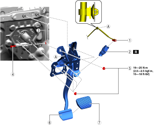
3. Remove in the order shown in the figure.
4. Install in the reverse order of removal.
5. If the brake pedal is replaced, perform the following procedure.
- (1) Connect the M-MDS.
-
- (2) Select the following item from the screen of the M-MDS.
-
- (3) Press [Start] for the vehicle identification.
-
- (4) Press the [Toolbox] tab.
-
- (5) Press the [Work Support] icon.
-
- (6) Press the [BRAKES] icon.
-
- (7) Press [Run] for Calibrating Pressure Sensor for DSC.
-
- (8) Perform the procedure according to the directions on the screen.
-
- (9) Drive the vehicle.
-
- (10) After 5 min or more of driving, verify that the DSC system is normal.
-
|
1
|
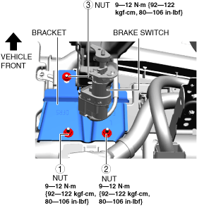
Brake switch connector and wiring harness
|
|
2
|
Brake switch
|
|
3
|
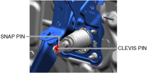
Snap pin
|
|
4
|
Clevis pin
|
|
5
|
Nut
|
|
6
|
Brake pedal
|
|
7
|
Pedal pad
|
Brake Pedal Removal Note
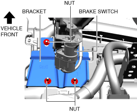
1. Remove the nuts. (With bracket)
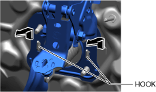
2. Move the brake pedal in the direction of the arrow shown in the figure, and remove it while avoiding the hooks.
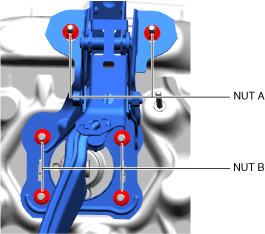
Brake Pedal Installation Note
1. Temporarily tighten nuts A.
2. Temporarily tighten nuts B.
3. Tighten nuts B to the specified torque.
4. Tighten nuts A to the specified torque.
5. Tighten the nuts in the order shown in the figure. (With bracket)
Snap Pin Installation Note
1. Install the snap pin as shown in the figure.
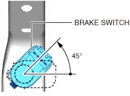
Brake Switch Installation Note
1. Inspect the brake pedal. (See BRAKE PEDAL INSPECTION.)
2. With the brake pedal fully released, insert the brake switch into the installation hole on the brake pedal.
-
Caution
-
• If the brake pedal arm is moved when securing the brake switch, the clearance between the brake pedal and brake switch may not be adjusted to the correct clearance. Be careful not to move the brake pedal arm when securing the brake switch.
3. Secure the brake switch by turning it counterclockwise 45°.