 |
am2zzw00006447
CYLINDER HEAD GASKET REPLACEMENT [MZ-CD 1.6]
id0110e3800700
1. Disconnect the negative battery cable.
2. Drain the engine coolant. (See ENGINE COOLANT REPLACEMENT [MZ-CD 1.6].)
3. Remove the drive belt auto tensioner. (See ENGINE DISASSEMBLY/ASSEMBLY [MZ-CD 1.6].)
4. Remove the windshield wiper arm and blade. (See WINDSHIELD WIPER ARM AND BLADE REMOVAL/INSTALLATION.)
5. Remove the cowl grille. (See COWL GRILLE REMOVAL/INSTALLATION.)
6. Remove the cowl panel. (See COWL PANEL REMOVAL/INSTALLATION.)
7. Remove the intake shutter valve, charge air cooler outlet hose. (See INTAKE-AIR SYSTEM REMOVAL/INSTALLATION [MZ-CD 1.6].)
8. Remove the charge air cooler inlet hose and intake air pipe No.1. (See INTAKE-AIR SYSTEM REMOVAL/INSTALLATION [MZ-CD 1.6].)
9. Remove the catalytic converter. (See EXHAUST SYSTEM REMOVAL/INSTALLATION [MZ-CD 1.6].)
10. Remove the intake air pipe No.2. (See INTAKE-AIR SYSTEM REMOVAL/INSTALLATION [MZ-CD 1.6].)
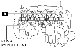
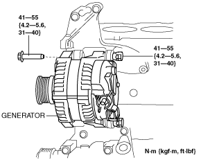
11. Remove the generator installation bolt shown in the figure.
am2zzw00006447
|
12. Remove the fuel filter component. (See FUEL FILTER REMOVAL/INSTALLATION [MZ-CD 1.6].)
13. Remove the EGR cooler with bypass valve and EGR valve. (See EGR VALVE REMOVAL/INSTALLATION [MZ-CD 1.6].)
14. Remove the thermostat. (See THERMOSTAT REMOVAL/INSTALLATION [MZ-CD 1.6].)
15. Remove the fuel injectors. (See FUEL INJECTOR REMOVAL/INSTALLATION [MZ-CD 1.6].)
16. Remove the coolant reserve tank with the hose still connected.
17. Remove the vacuum pump. (See VACUUM PUMP REMOVAL/INSTALLATION [MZ-CD 1.6].)
18. Disconnect the ventilation hose from the cylinder head cover.
19. Remove the timing belt. (See TIMING BELT REMOVAL/INSTALLATION [MZ-CD 1.6].)
20. Remove the HLA. (See HYDRAULIC LASH ADJUSTER (HLA) REMOVAL/INSTALLATION [MZ-CD 1.6].)
21. Remove the Supply pump. (See SUPPLY PUMP REMOVAL/INSTALLATION [MZ-CD 1.6].)
22. Remove the oil inlet pipe. (See EXHAUST SYSTEM REMOVAL/INSTALLATION [MZ-CD 1.6].)
23. Disconnect the oil outlet pipe from the oil cooler.
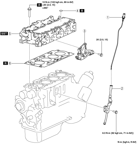
24. Remove in the order indicated in the table.
25. Install in the reverse order of removal.
am2zzw00006436
|
|
1
|
Dipstick
|
|
2
|
Dipstick pipe
|
|
3
|
Generator bracket
|
|
4
|
O-ring
(See O-ring Removal Note.)
(See O-ring Installation Note.)
|
|
5
|
Lower cylinder head
|
|
6
|
Cylinder head gasket
|
O-ring Removal Note
am2zzw00007112
|
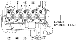
Lower Cylinder Head Removal Note
1. Loosen the cylinder head bolts in 2—3 passes in the order shown in the figure.
am2zzw00007113
|
Cylinder Head Gasket Installation Note
|
Number of notch |
Piston protrusion |
Gasket thickness |
|---|---|---|
|
1
|
0.684—0.734 mm {0.0270—0.0288 in}
|
1.35 mm {0.0531 in}
|
|
2
|
0.533—0.634 mm {0.0210—0.0249 in}
|
1.25 mm {0.0492 in}
|
|
3
|
0.634—0.684 mm {0.0250—0.0269 in}
|
1.30 mm {0.0512 in}
|
|
4
|
0.734—0.784 mm {0.0289—0.0308 in}
|
1.40 mm {0.0551 in}
|
|
5
|
0.784—0.886 mm {0.0309—0.0348 in}
|
1.45 mm {0.0571 in}
|
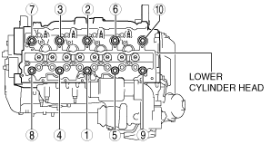
Lower Cylinder Head Installation Note
1. Tighten the new cylinder head installation bolts using the SST (49 D032 316) in three steps in the order shown in the figure.
am2zzw00007114
|
O-ring Installation Note
am2zzw00007112
|