SHROUD PANEL REMOVAL/INSTALLATION
id091000801900
1. Disconnect the negative battery cable. (See NEGATIVE BATTERY CABLE DISCONNECTION/CONNECTION [SKYACTIV-G 1.5, SKYACTIV-G 2.0, SKYACTIV-G 2.5].) (See NEGATIVE BATTERY CABLE DISCONNECTION/CONNECTION [MZR 1.6].) (See NEGATIVE BATTERY CABLE DISCONNECTION/CONNECTION [SKYACTIV-D 2.2].) (See NEGATIVE BATTERY CABLE DISCONNECTION/CONNECTION [SKYACTIV-D 1.5].)
2. Remove the following parts:
- (1) Set plate (See SET PLATE REMOVAL/INSTALLATION.)
- (2) Front bumper (See FRONT BUMPER REMOVAL.) (See FRONT BUMPER INSTALLATION.)
- (3) Front combination light (See FRONT COMBINATION LIGHT REMOVAL/INSTALLATION.)
- (4) Active air shutter (With active air shutter system) (See ACTIVE AIR SHUTTER REMOVAL/INSTALLATION.)
- (5) Shroud upper member (See SHROUD UPPER MEMBER REMOVAL/INSTALLATION.)
- (6) Bonnet lock (See BONNET LATCH REMOVAL/INSTALLATION.)
- (7) Intake air guide (See INTAKE AIR GUIDE REMOVAL/INSTALLATION.)
- (8) Front energy-absorbing form (With front energy-absorbing form) (See ENERGY-ABSORBING FORM REMOVAL/INSTALLATION.)
- (9) Charge air cooler (SKYACTIV-D 2.2) (See CHARGE AIR COOLER REMOVAL/INSTALLATION [SKYACTIV-D 2.2].)
- (10) Seal plate (With seal plate) (See SEAL PLATE REMOVAL/INSTALLATION.)
- (11) Front under cover No.1 (See FRONT UNDER COVER No.1 REMOVAL/INSTALLATION.)
- (12) Bumper stiffener lower (See BUMPER STIFFENER LOWER REMOVAL/INSTALLATION.)
-
Caution
-
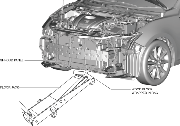
• The front bumper reinforcement supports the shroud panel. After removing the front bumper reinforcement, an excessive load applied to the shroud panel could result in damage. When removing the front bumper reinforcement, always use a floor jack to support the shroud panel.
3. Support the shroud panel using a floor jack.
4. Remove the following parts:
- (1) Front bumper reinforcement (See FRONT BUMPER REINFORCEMENT REMOVAL/INSTALLATION.)
- (2) Ambient temperature sensor (See AMBIENT TEMPERATURE SENSOR REMOVAL/INSTALLATION [FULL-AUTO AIR CONDITIONER].) (See AMBIENT TEMPERATURE SENSOR INSPECTION [MANUAL AIR CONDITIONER].)
- (3) Crash zone sensor (See CRASH ZONE SENSOR REMOVAL/INSTALLATION.)
- (4) Radar unit (With mazda radar cruise control (MRCC) system) (See RADAR UNIT REMOVAL/INSTALLATION.)
5. Remove the wiring harness clips secured to the shroud panel.
-
Warning
-
• Secure the bonnet stay using packing tape so that it does not detach. Otherwise, the bonnet may fall and cause injury.
6. Relocate the bonnet stay to the position shown in the figure.
-
Warning
-
• Remove the radiator from the shroud panel using two people. Otherwise, the radiator may fall and cause injury.
7. Remove the floor jack which has supported the shroud panel.
8. Press down the tabs shown in the figure in the direction of the arrow, pull out the upper mount rubber bracket toward the vehicle rear, and remove it.
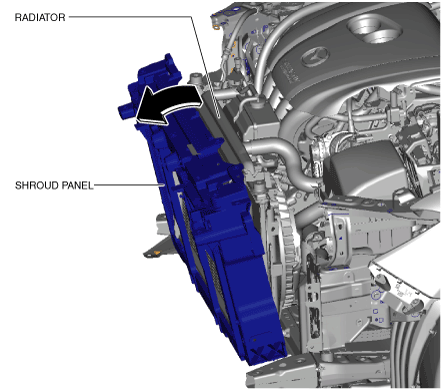
9. Hold the upper part of the radiator by hand and tilt the shroud panel toward the vehicle front.
10. Move the shroud panel to the lower side with the radiator held by hand, detach it from the radiator mount guide, and remove the shroud panel toward the vehicle front.
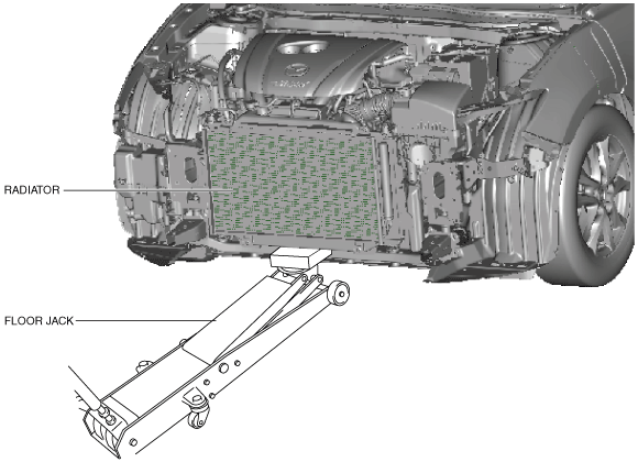
11. Support the radiator using a floor jack at the position shown in the figure.
12. Install in the reverse order of removal.
13. Adjust the headlight aiming. (See HEADLIGHT AIMING.)
14. Adjust the radar unit aiming. (With mazda radar cruise control (MRCC) system) (See RADAR UNIT AIMING.)