DTC
System malfunction location
Page
M-MDS display
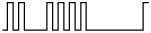
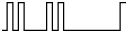
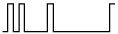
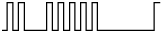
Air bag system warning light
Flashing pattern
Priority ranking
B1046
24
17
Short to the driver-side curtain air bag module circuit and other air bag module circuits
B1047
22
15
Short to the driver-side side air bag module circuit and other air bag module circuits
B1048
21
9
Short to the passenger-side air bag module circuit and other air bag module circuits
B1049
34

12
Short to the passenger-side pre-tensioner seat belt circuit and other air bag module circuits
B104B
43

8
Short to the driver-side side air bag sensor circuit and other sensor circuits
B104C
44

7
Short to the passenger-side side air bag sensor circuit and other sensor circuits
B104D
42

6
Short to the crash zone sensor circuits and other sensor circuits
B104E
43
8
Driver-side side air bag sensor circuit short to power supply or body ground
B104F
44
7
Passenger-side side air bag sensor internal malfunction
B1050
Passenger-side side air bag sensor circuit short to power supply or body ground
B1051
43
8
Driver-side side air bag sensor internal malfunction
B1054
33

13
Short to the driver-side pre-tensioner seat belt circuit and other air bag module circuits
B1055
23

14
Short to the passenger-side side air bag module circuit and other air bag module circuits
B1056
25
16
Short to the passenger-side curtain air bag module circuit and other air bag module circuits
B1057
19

10
Short to the driver-side air bag module circuit and other air bag module circuits
B10A6
35

11
Lap pre-tensioner seat belt circuit open circuit or resistance high
B10A7
Lap pre-tensioner seat belt circuit short to power supply
B10A8
Lap pre-tensioner seat belt circuit short to body ground
B10A9
Lap pre-tensioner seat belt circuit resistance low
B10AA
Short to the lap pre-tensioner seat belt circuit and other air bag module circuits
B1231
13
3
SAS control module activation (deployment) control freeze
(See DTC B1231.)
B1317
―
Continuously illuminated
1
SAS control module power supply voltage increases (16 V or more)
(See DTC B1317, B1318.)
B1318
SAS control module power supply voltage decreases (8 V or less)
B1342
12

2
SAS control module internal malfunction
(See DTC B1342.)
―
Continuously illuminated
1
B1868
―
Continuously illuminated
1
Air bag system warning light malfunction
(See DTC B1868.)
B1871
56

18
PAD switch system circuit disabled
(See DTC B1871.)
B1877
33
13
Driver-side pre-tensioner seat belt circuit open circuit or resistance high
B1878
Driver-side pre-tensioner seat belt circuit short to power supply
B1879
Driver-side pre-tensioner seat belt circuit short to body ground
B1881
34
12
Passenger-side pre-tensioner seat belt circuit open circuit or resistance high
B1882
Passenger-side pre-tensioner seat belt circuit short to power supply
B1883
Passenger-side pre-tensioner seat belt circuit short to body ground
B1884
18

19
Passenger air bag deactivation (PAD) indicator circuit open or short to body ground
(See DTC B1884, B1890.)
B1885
33
13
Driver-side pre-tensioner seat belt circuit resistance low
B1886
34
12
Passenger-side pre-tensioner seat belt circuit resistance low
B1890
18
19
Passenger air bag deactivation (PAD) indicator circuit short to power supply
(See DTC B1884, B1890.)
B1916
19
10
Driver-side air bag module circuit short to power supply
B1925
21
9
Passenger-side air bag module circuit short to power supply
B1932
19
10
Driver-side air bag module circuit open circuit or resistance high
B1933
21
9
Passenger-side air bag module circuit open circuit or resistance high
B1934
19
10
Driver-side air bag module circuit resistance low
B1935
21
9
Passenger-side air bag module circuit resistance low
B1936
19
10
Driver-side air bag module circuit short to body ground
B1938
21
9
Passenger-side air bag module circuit short to body ground
B1992
22
15
Driver-side side air bag module circuit short to power supply
B1993
Driver-side side air bag module circuit short to body ground
B1994
Driver-side side air bag module circuit open circuit or resistance high
B1995
Driver-side side air bag module circuit resistance low
B1996
23
14
Passenger-side side air bag module circuit short to power supply
B1997
Passenger-side side air bag module circuit short to body ground
B1998
Passenger-side side air bag module circuit open circuit or resistance high
B1999
Passenger-side side air bag module circuit resistance low
B2226
42
6
Crash zone sensor internal malfunction
B2227
Crash zone sensor (communication error)
B2477
―
Flashing
4
No configuration
(See DTC B2477.)
54

5
Configuration error
B2773
24
17
Driver-side curtain air bag module circuit resistance low
B2774
Driver-side curtain air bag module circuit open circuit or resistance high
B2775
Driver-side curtain air bag module circuit short to body ground
B2776
Driver-side curtain air bag module circuit short to power supply
B2777
25
16
Passenger-side curtain air bag module circuit resistance low
B2778
Passenger-side curtain air bag module circuit open circuit or resistance high
B2779
Passenger-side curtain air bag module circuit short to body ground
B2780
Passenger-side curtain air bag module circuit short to power supply
B2855
42
6
Crash zone sensor circuit short to power supply or body ground
B2856
Crash zone sensor ID mismatch
(See DTC B2856, B2886, B2887.)
B2886
44
7
Passenger-side side air bag sensor ID mismatch
B2887
43
8
Driver-side side air bag sensor ID mismatch
B2BCD
―
Continuously illuminated
1
SAS control module connectors are poorly connected
(See DTC B2BCD.)
C1280*
―
―
―
Yaw rate sensor in SAS control module is signal error
(See DTC C1280, C1282, C2770.)
C1282*
Low-G (XY) sensor (lateral-G) in SAS control module is signal error
C2770*
Low-G (XY) sensor (forward-G) in SAS control module is signal error
U0073
―
Continuously illuminated
1
CAN communication error
U0155
Communication error to instrument cluster
U2017
43
8
Driver-side side air bag sensor (communication error)
U2018
44
7
Passenger-side side air bag sensor (communication error)
U2527*
―
―
―
DSC HU/CM communication fault
(See DTC U2527.)
