|
1
|
CONFIRM PCM DTC
• Perform the PCM DTC inspection using the M-MDS.
• Are any DTCs present?
|
Yes
|
Go to the applicable DTC inspection.
|
|
No
|
Go to the next step.
|
|
2
|
INSPECT BATTERY
• Is there any malfunction?
|
Yes
|
Recharge or replace the battery, then go to Step 13.
|
|
No
|
Go to the next step.
|
|
3
|
INSPECT GENERATOR
• Is there any malfunction?
|
Yes
|
Replace the generator, then go to Step 13.
|
|
No
|
Go to the next step.
|
|
4
|
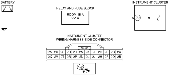
INSPECT INSTRUMENT CLUSTER CONNECTOR AND TERMINALS
• Switch the ignition to off.
• Disconnect the negative battery cable.
• Disconnect the instrument cluster connector.
• Inspect the connector for poor connection (such as damaged/pulled-out pins, and corrosion).
• Is there any malfunction?
|
Yes
|
Repair or replace the connector or terminals, then go to Step 13.
|
|
No
|
Go to the next step.
|
|
5
|
VERIFY MALFUNCTIONING LOCATION
• Verify that the instrument cluster connector is disconnected.
• Reconnect the negative battery cable.
• Switch the ignition to ON.
• Measure the voltage at the following terminals (wiring harness-side):
-
― Instrument cluster terminal 2U
― Instrument cluster terminal 1L
• Is the voltage B+?
|
Yes
|
Go to Step 13.
|
|
No
|
If terminal 2U voltage is not B+:
• Go to the next step.
If terminal 1L voltage is not B+:
• Go to Step 7.
|
|
6
|
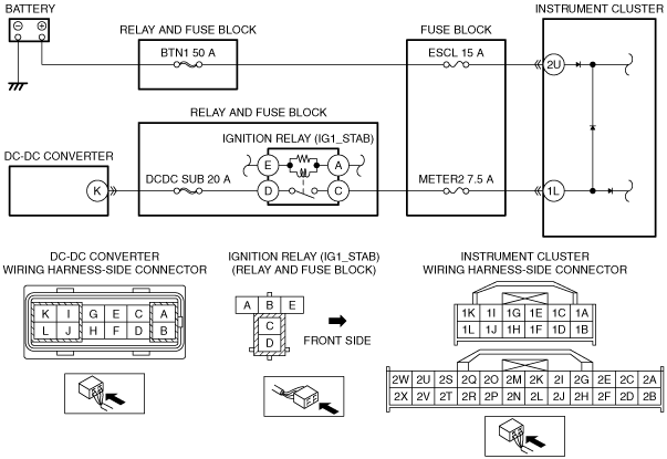
INSPECT INSTRUMENT CLUSTER POWER SUPPLY CIRCUIT FOR OPEN CIRCUIT AND SHORT TO GROUND
• Switch the ignition to off.
• Disconnect the negative battery cable.
• Inspect the ESCL 15 A fuse and BTN1 50 A fuse.
• Is there any malfunction?
|
Yes
|
If the fuse is blown:
• Repair or replace the wiring harness for a possible short to ground.
• Replace the fuse.
If the fuse is deterioration:
• Replace the fuse.
Go to Step 13.
|
|
No
|
Repair or replace the wiring harness for a possible open circuit, then go to Step 13.
|
|
7
|
VERIFY MALFUNCTIONING LOCATION
• Verify that the instrument cluster connector is disconnected.
• Measure the voltage at the ignition relay (IG1_STAB) terminal D (wiring harness-side).
• Is the voltage B+?
|
Yes
|
Go to the next step.
|
|
No
|
Go to Step 9.
|
|
8
|
INSPECT IGNITION RELAY (IG1_STAB)
• Switch the ignition to off.
• Disconnect the negative battery cable.
• Remove the ignition relay (IG1_STAB).
• Inspect the ignition relay (IG1_STAB).
• Is there any malfunction?
|
Yes
|
Replace the ignition relay (IG1_STAB), then go to Step 13.
|
|
No
|
Repair or replace the wiring harness between ignition relay (IG1_STAB) and instrument cluster.
Replace the fuse if necessary, then go to Step 13.
|
|
9
|
INSPECT DC-DC CONVERTER CONNECTOR AND TERMINALS
• Switch the ignition to off.
• Disconnect the negative battery cable.
• Disconnect the DC-DC converter connector.
• Inspect the connector for poor connection (such as damaged/pulled-out pins, and corrosion).
• Is there any malfunction?
|
Yes
|
Repair or replace the connector or terminals, then go to Step 13.
|
|
No
|
Go to the next step.
|
|
10
|
INSPECT WIRING HARNESS BETWEEN DC-DC CONVERTER AND IGNITION RELAY (IG1_STAB) FOR SHORT TO GROUND
• Verify that the DC-DC converter connector is disconnected.
• Inspect for continuity between ignition relay (IG1_STAB) terminal D (wiring harness-side) and body ground.
• Is there continuity?
|
Yes
|
Repair or replace the wiring harness for a possible short to ground.
Replace the fuse if necessary, then go to Step 13.
|
|
No
|
Go to the next step.
|
|
11
|
INSPECT WIRING HARNESS BETWEEN DC-DC CONVERTER AND IGNITION RELAY (IG1_STAB) FOR OPEN CIRCUIT
• Verify that the DC-DC converter connector is disconnected.
• Inspect for continuity between DC-DC converter terminal K (wiring harness-side) and ignition relay (IG1_STAB) terminal D (wiring harness-side).
• Is there continuity?
|
Yes
|
Go to the next step.
|
|
No
|
Repair or replace the wiring harness for a possible open circuit.
Replace the fuse if necessary, then go to Step 13.
|
|
12
|
INSPECT DC-DC CONVERTER
• Inspect the DC-DC converter.
• Is there any malfunction?
|
Yes
|
Replace the DC-DC converter, then go to the next step.
|
|
No
|
Go to the next step.
|
|
13
|
VERIFY TROUBLESHOOTING COMPLETED
• Make sure to reconnect all disconnected connectors.
• Reconnect the negative battery cable.
• Clear the DTC from the instrument cluster using the M-MDS.
• Perform the instrument cluster DTC inspection using the M-MDS.
• Is the same DTC present?
|
Yes
|
Repeat the inspection from Step 1.
• If the malfunction recurs, replace the instrument cluster.
Go to the next step.
|
|
No
|
Go to the next step.
|
|
14
|
VERIFY THAT NO OTHER DTCs ARE PRESENT
• Are any DTCs present?
|
Yes
|
Go to the applicable DTC inspection.
|
|
No
|
DTC troubleshooting completed.
|