RESISTOR REMOVAL/INSTALLATION
id074000800700
L.H.D. (Hexagon Head Screw Type)
1. Remove the battery and battery tray. (See BATTERY REMOVAL/INSTALLATION [ZY, Z6].) (See BATTERY REMOVAL/INSTALLATION [LF, L3].)
2. Remove the following parts:
-
(1) Side wall (See SIDE WALL REMOVAL/INSTALLATION.)
-
(2) Front scuff plate (LH) (See FRONT SCUFF PLATE REMOVAL/INSTALLATION.)
-
(3) Front side trim (LH) (See FRONT SIDE TRIM REMOVAL/INSTALLATION.)
-
(4) Bonnet release lever (See BONNET LATCH AND RELEASE LEVER REMOVAL/INSTALLATION.)
-
(5) Lower panel (See LOWER PANEL REMOVAL/INSTALLATION.)
-
(6) Column cover (See COLUMN COVER REMOVAL/INSTALLATION.)
-
(7) Meter hood (See METER HOOD REMOVAL/INSTALLATION.)
-
(8) Instrument cluster (See INSTRUMENT CLUSTER REMOVAL/INSTALLATION.)
-
(9) Steering shaft (See STEERING WHEEL AND COLUMN REMOVAL/INSTALLATION.)
-
(10) Accelerator pedal (See ACCELERATOR PEDAL REMOVAL/INSTALLATION [ZY, Z6].) (See ACCELERATOR PEDAL REMOVAL/INSTALLATION [LF, L3].)
-
(11) Brake pedal (See BRAKE PEDAL REMOVAL/INSTALLATION.)
3. Disconnect the blower motor cooling pipe connected to the blower motor.
4. Disconnect the resistor connector.
5. Remove the resistor.
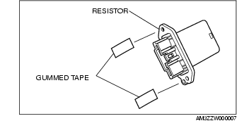
6. Affix the packing tape to the thread hole area as shown in the figure. (Do not wrap the packing tape around the backside of the resistor.)
7. Stick the screw into the thread hole.
8. Set the resistor to the A/C unit and temporarily tighten the hexagon head screw.
-
Caution
-
• While setting the resistor, be careful not to damage the pattern surface. Otherwise it could cause a resistor operation malfunction.
9. Tighten the lower screw.
10. Tighten the hexagon head screw.
11. Connect the resistor connector.
12. Connect the blower motor cooling pipe.
13. Install the following parts:
-
(1) Brake pedal (See BRAKE PEDAL REMOVAL/INSTALLATION.)
-
(2) Accelerator pedal (See ACCELERATOR PEDAL REMOVAL/INSTALLATION [ZY, Z6].) (See ACCELERATOR PEDAL REMOVAL/INSTALLATION [LF, L3].)
-
(3) Steering shaft (See STEERING WHEEL AND COLUMN REMOVAL/INSTALLATION.)
-
(4) Meter hood (See METER HOOD REMOVAL/INSTALLATION.)
-
(5) Instrument cluster (See INSTRUMENT CLUSTER REMOVAL/INSTALLATION.)
-
(6) Column cover (See COLUMN COVER REMOVAL/INSTALLATION.)
-
(7) Lower panel (See LOWER PANEL REMOVAL/INSTALLATION.)
-
(8) Bonnet release lever (See BONNET LATCH AND RELEASE LEVER REMOVAL/INSTALLATION.)
-
(9) Front scuff plate (LH) (See FRONT SCUFF PLATE REMOVAL/INSTALLATION.)
-
(10) Front side trim (LH) (See FRONT SIDE TRIM REMOVAL/INSTALLATION.)
-
(11) Side wall (See SIDE WALL REMOVAL/INSTALLATION.)
14. Install the battery and battery tray. (See BATTERY REMOVAL/INSTALLATION [ZY, Z6].) (See BATTERY REMOVAL/INSTALLATION [LF, L3].)
L.H.D. (Not Hexagon Head Screw Type)
1. Disconnect the negative battery cable.
2. Remove the two nuts securing the cooler hose (LO).
3. Remove the following parts:
-
(1) Front doors (See FRONT DOOR REMOVAL/INSTALLATION.)
-
(2) Console (See CONSOLE REMOVAL/INSTALLATION.)
-
(3) Shift lever component (MTX) (See SHIFT MECHANISM REMOVAL/INSTALLATION.)
-
(4) Selector lever component (ATX) (See SELECTOR LEVER COMPONENT REMOVAL/INSTALLATION.)
-
(5) Decoration panel (See DECORATION PANEL REMOVAL/INSTALLATION.)
-
(6) Front scuff plate (See FRONT SCUFF PLATE REMOVAL/INSTALLATION.)
-
(7) Front side trim (See FRONT SIDE TRIM REMOVAL/INSTALLATION.)
-
(8) Glove compartment (See GLOVE COMPARTMENT REMOVAL/INSTALLATION.)
-
(9) Shower ducts (LH, RH) (See A/C UNIT REMOVAL/INSTALLATION.)
-
(10) PJB (See PASSENGER JUNCTION BOX (PJB) REMOVAL/INSTALLATION.)
-
(11) Lower panel (See LOWER PANEL REMOVAL/INSTALLATION.)
-
(12) Column cover (See COLUMN COVER REMOVAL/INSTALLATION.)
-
(13) Meter hood (See METER HOOD REMOVAL/INSTALLATION.)
-
(14) Instrument cluster (See INSTRUMENT CLUSTER REMOVAL/INSTALLATION.)
-
(15) Steering shaft (See STEERING WHEEL AND COLUMN REMOVAL/INSTALLATION.)
-
(16) A-pillar trim (See A-PILLAR TRIM REMOVAL/INSTALLATION.)
-
(17) Center panel module (See CENTER PANEL MODULE REMOVAL/INSTALLATION.)
-
(18) Cowl grille (See COWL GRILLE REMOVAL/INSTALLATION.)
-
(19) Cowl panel (See COWL PANEL REMOVAL/INSTALLATION.)
-
(20) Windshield wiper arm and blade (See WINDSHIELD WIPER ARM AND BLADE REMOVAL/INSTALLATION.)
-
(21) Windshield wiper motor (See WINDSHIELD WIPER MOTOR REMOVAL/INSTALLATION.)
4. Disconnect the air mix wire from the air mix link and wire clamp. (Manual air conditioner)
5. Disconnect the airflow mode wire from the airflow mode main link and wire clamp. (Manual air conditioner)
6. Disconnect the following connectors:
-
- Blower motor connector
-
- Power MOS FET connector (Full-auto air conditioner)
-
- Evaporator temperature sensor connector
-
- Air intake actuator connector
-
- Air mix actuator connector (Full-auto air conditioner)
-
- Airflow mode actuator connector (Full-auto air conditioner)
7. Remove the rear heat duct (1).
8. Remove the heater case. (See A/C UNIT REMOVAL/INSTALLATION.)
9. Remove the dashboard. (See DASHBOARD REMOVAL/INSTALLATION.)
10. Move the A/C unit to the right and remove the resistor.
-
Caution
-
• While moving the A/C unit, do not apply excessive force. Otherwise it will result in deformation of the refrigerant piping or refrigerant gas leakage.
11. Install in the reverse order of removal.
R.H.D.
1. Disconnect the negative battery cable.
2. Remove the following parts:
-
(1) Decoration panel (See DECORATION PANEL REMOVAL/INSTALLATION.)
-
(2) Front scuff plate (See FRONT SCUFF PLATE REMOVAL/INSTALLATION.)
-
(3) Front side trim (See FRONT SIDE TRIM REMOVAL/INSTALLATION.)
-
(4) Glove compartment (See GLOVE COMPARTMENT REMOVAL/INSTALLATION.)
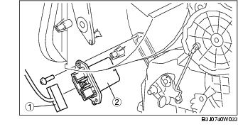
3. Remove in the order indicated in the table.
|
1
|
Resister connector
|
|
2
|
Resister
|
4. Install in the reverse order of removal.