BACKUP POWER SUPPLY REMOVAL/INSTALLATION
id092100909000
4SD
1. Operate the door lock actuator using the following procedure and deplete the energy stored in the backup power supply.
-
Note
-
• If the energy stored in the backup power supply has already been depleted, the door lock actuator does not operate. As this does not indicate an improper procedure, continue to perform the procedure as indicated.
- (1) Remove the D.LOCK 25A fuse.
-
- (2) Close the front door (driver's side)
-
- (3) Repeat the lock/unlock operation of the door lock switch (driver's side) until all the door lock knobs do not move. (With door lock switch)
-
- (4) Repeat the lock/unlock operation of the door lock knob (driver's side) until the door lock knobs other than the driver's seat do not move. (Without door lock switch)
-
2. Disconnect the negative battery terminal. (See NEGATIVE BATTERY TERMINAL DISCONNECTION/CONNECTION.)
3. Lower the rear seat back.
4. Remove the following parts:
- (1) Rear scuff plate (See REAR SCUFF PLATE REMOVAL/INSTALLATION.)
-
- (2) Rear seat cushion (See REAR SEAT CUSHION REMOVAL/INSTALLATION.)
-
- (3) Rear seat side back (See REAR SEAT SIDE BACK REMOVAL/INSTALLATION.)
-
- (4) Tire house trim (See TIRE HOUSE TRIM REMOVAL/INSTALLATION.)
-
- (5) C-pillar trim (See C-PILLAR TRIM REMOVAL/INSTALLATION.)
-
- (6) High-mount brake light (See HIGH-MOUNT BRAKE LIGHT REMOVAL/INSTALLATION.)
-
- (7) Rear package trim (See REAR PACKAGE TRIM REMOVAL/INSTALLATION.)
-
- (8) Rear body control module (RBCM) (See REAR BODY CONTROL MODULE (RBCM) REMOVAL/INSTALLATION.)
-
- (9) Upper anchor installation bolts on the rear center seat belt (See REAR CENTER SEAT BELT REMOVAL/INSTALLATION.)
-
- (10) Rear body control module (RBCM) bracket and backup power supply as a single unit (See REAR BODY CONTROL MODULE (RBCM) BRACKET REMOVAL/INSTALLATION.)
-
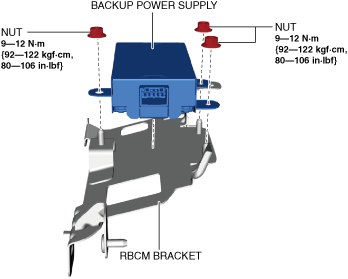
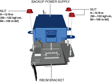
5. Remove the nuts.
6. Remove the backup power supply.
7. Install in the reverse order of removal.
WGN
1. Operate the door lock actuator using the following procedure and deplete the energy stored in the backup power supply.
-
Note
-
• If the energy stored in the backup power supply has already been depleted, the door lock actuator does not operate. As this does not indicate an improper procedure, continue to perform the procedure as indicated.
- (1) Remove the D.LOCK 25A fuse.
-
- (2) Close the front door (driver's side)
-
- (3) Repeat the lock/unlock operation of the door lock switch (driver's side) until all the door lock knobs do not move. (With door lock switch)
-
- (4) Repeat the lock/unlock operation of the door lock knob (driver's side) until the door lock knobs other than the driver's seat do not move. (Without door lock switch)
-
2. Disconnect the negative battery terminal. (See NEGATIVE BATTERY TERMINAL DISCONNECTION/CONNECTION.)
3. Remove the following parts:
- (1) Rear scuff plate (LH) (See REAR SCUFF PLATE REMOVAL/INSTALLATION.)
-
- (2) Trunk covering (See TRUNK COVERING REMOVAL/INSTALLATION.)
-
- (3) Trunk board (See TRUNK BOARD REMOVAL/INSTALLATION.)
-
- (4) Trunk side pocket (See TRUNK SIDE POCKET REMOVAL/INSTALLATION.)
-
- (5) Trunk end trim (See TRUNK END TRIM REMOVAL/INSTALLATION.)
-
- (6) Rear seat belt lower anchor installation bolt (LH) (See REAR SEAT BELT REMOVAL/INSTALLATION.)
-
- (7) Trunk side upper trim (LH) (See TRUNK SIDE UPPER TRIM REMOVAL/INSTALLATION.)
-
- (8) Trunk side trim (LH) (See TRUNK SIDE TRIM REMOVAL/INSTALLATION.)
-
- (9) Rear body control module (RBCM), rear body control module (RBCM) bracket, and backup power supply as a single unit (See REAR BODY CONTROL MODULE (RBCM) BRACKET REMOVAL/INSTALLATION.)
-
4. Remove the nuts.
5. Remove the backup power supply.
6. Install in the reverse order of removal.