 |
am6zzw00015688
REAR BODY CONTROL MODULE (RBCM) BRACKET REMOVAL/INSTALLATION
id094000003000
4SD
1. Disconnect the negative battery terminal. (See NEGATIVE BATTERY TERMINAL DISCONNECTION/CONNECTION.)
2. Lower the rear seat back.
3. Remove the following parts:
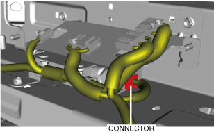
4. Disconnect the connector. (with backup power supply)
am6zzw00015688
|
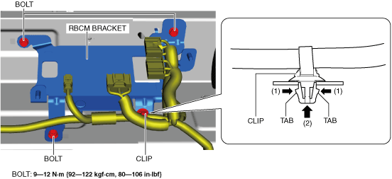
5. Remove the bolts.
am6xuw00009319
|
6. While pressing the tabs of the clip in the direction of the arrows (1) shown in the figure, pull the clip in the direction of the arrow (2) shown in the figure to remove the clip from the rear body control module (RBCM) bracket.
7. Remove the backup power supply. (with backup power supply) (See BACKUP POWER SUPPLY REMOVAL/INSTALLATION.)
8. Remove the rear body control module (RBCM) bracket.
9. Install in the reverse order of removal.
WGN
1. Disconnect the negative battery terminal. (See NEGATIVE BATTERY TERMINAL DISCONNECTION/CONNECTION.)
2. Remove the following parts:
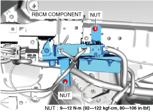
3. Remove the nuts.
am6zzw00015689
|
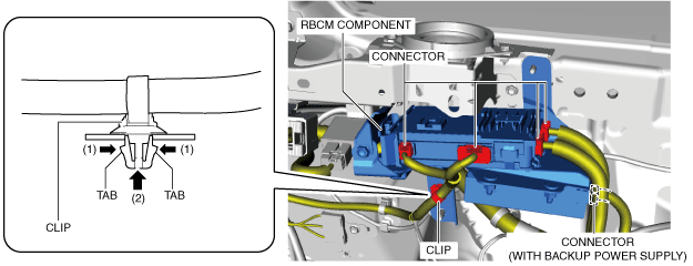
4. Disconnect the connectors.
am6zzw00015690
|
5. While pressing the tabs of the clip in the direction of the arrows (1) shown in the figure, pull the clip in the direction of the arrow (2) shown in the figure to remove the clip from the rear body control module (RBCM) bracket.
6. Remove the rear body control module (RBCM) component.
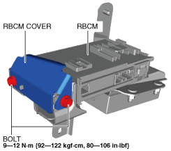
7. Remove the bolts.
am6zzw00015691
|
8. Remove the rear body control module (RBCM) cover.
9. While pressing the rear body control module (RBCM) tab in the direction of arrow (1) shown in the figure, pull it in the direction of arrow (2) to detach the tab from the rear body control module (RBCM) bracket.
am6zzw00015692
|
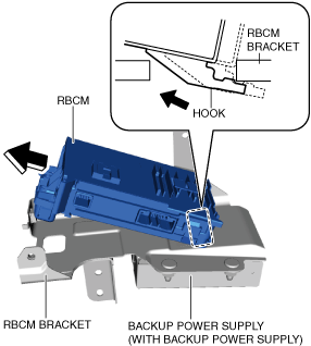
10. Pull the rear body control module (RBCM) up in the direction of the arrow to detach the hook from the rear body control module (RBCM) bracket.
am6zzw00015693
|
11. Remove the rear body control module (RBCM).
12. Remove the backup power supply. (with backup power supply) (See BACKUP POWER SUPPLY REMOVAL/INSTALLATION.)
13. Remove the rear body control module (RBCM) bracket.
14. Install in the reverse order of removal.