1. : Mazda SST number
2. : Global SST number
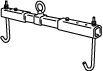
1: 49 UN30 3050
2: 303–050
Engine lifting bracket
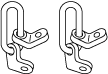
1: 49 L017 5A0
2: –
Support hanger
ENGINE DISASSEMBLY/ASSEMBLY [SKYACTIV-D 2.2]
id0110s5800500
Special Service Tool (SST)
|
1. : Mazda SST number
2. : Global SST number
|
|||
|
1: 49 UN30 3050
2: 303–050
Engine lifting bracket
|
|
1: 49 L017 5A0
2: –
Support hanger
|
|
Replacement Part
|
Washer
Quantity: 2
Location of use: Exhaust gas pressure sensor No.1 component
|
Gasket
Quantity: 2
Location of use: Water pipe
|
Bolt
Quantity: 1
Location of use: Noise suppression cover (No.3)
|
|
Gasket
Quantity: 1
Location of use: Water pump component
|
Hose
Quantity: 2
Location of use: Exhaust gas pressure sensor No.2 component
|
Clip
Quantity: 2
Location of use: Exhaust gas pressure sensor No.2 component
|
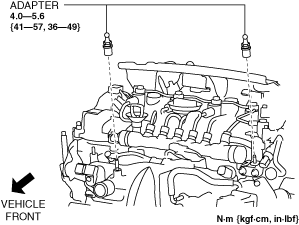
1. Remove the adapter.
ac5wzw00009332
|
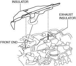
2. Remove the insulator shown in the figure.
ac5wzw00005016
|
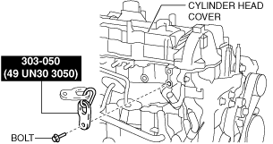
3. Install the SST to the position shown in the figure using the following bolt and washer.
ac5wzw00006602
|
4. Install the SST to the position shown in the figure using the following bolt.
ac5wzw00006603
|
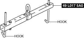
5. Engage the hooks of the SST (49 L017 5A0) to the SST (49 UN30 3050).
ac5wzw00005215
|
6. To ensure the safety of the work (control engine and transaxle sway), set a hoist as shown in the figure.
ac5jjw00005202
|
7. Remove the exhaust system. (See EXHAUST SYSTEM REMOVAL/INSTALLATION [SKYACTIV-D 2.2].)
8. Remove the transfer bracket and transfer. (4WD) (See TRANSFER REMOVAL/INSTALLATION [D66MX-R] (MTX).) (See TRANSFER REMOVAL/INSTALLATION [GW6AX-EL (SKYACTIV-D 2.2)] (ATX).)
9. Remove the turbocharger. (See TURBOCHARGER REMOVAL/INSTALLATION [SKYACTIV-D 2.2].)
10. Remove the vacuum chamber. (See VACUUM CHAMBER REMOVAL/INSTALLATION [SKYACTIV-D 2.2].)
11. Remove the following emission system related parts:
12. Remove the bracket No.1. (See FRONT DRIVE SHAFT REMOVAL/INSTALLATION.)
13. Remove the starter. (See STARTER REMOVAL/INSTALLATION [SKYACTIV-D 2.2].)
14. Remove the generator. (See GENERATOR REMOVAL/INSTALLATION [SKYACTIV-D 2.2].)
15. Remove the drive belt auto tensioner. (See DRIVE BELT AUTO TENSIONER REMOVAL/INSTALLATION [SKYACTIV-D 2.2].)
16. Lock the drive plate against rotation using the crankshaft pulley lock bolt. (ATX)
17. Remove the torque converter installation nut from the starter installation hole. (See AUTOMATIC TRANSAXLE REMOVAL/INSTALLATION [GW6A-EL] (2WD).) (See AUTOMATIC TRANSAXLE REMOVAL/INSTALLATION [GW6AX-EL (SKYACTIV-D 2.2)] (4WD).)
18. Disconnect the engine and transaxle, and lower only the engine from the engine lifter. (See MANUAL TRANSAXLE REMOVAL/INSTALLATION [D66M-R] (MTX, 2WD).) (See MANUAL TRANSAXLE REMOVAL/INSTALLATION [D66MX-R] (MTX, 4WD).) (See AUTOMATIC TRANSAXLE REMOVAL/INSTALLATION [GW6A-EL] (ATX, 2WD).) (See AUTOMATIC TRANSAXLE REMOVAL/INSTALLATION [GW6AX-EL (SKYACTIV-D 2.2)] (ATX, 4WD).)
19. Remove the clutch cover and clutch disc. (See CLUTCH UNIT REMOVAL/INSTALLATION [D66M-R, D66MX-R] (MTX).)
20. Remove the intake-air system. (See INTAKE-AIR SYSTEM REMOVAL/INSTALLATION [SKYACTIV-D 2.2].)
21. Remove the following fuel system related parts:
22. Remove the glow plugs. (See GLOW PLUG REMOVAL/INSTALLATION [SKYACTIV-D 2.2].)
23. Remove the vacuum pump. (See VACUUM PUMP REMOVAL/INSTALLATION [SKYACTIV-D 2.2].)
24. Remove the oil cooler. (See OIL COOLER REMOVAL/INSTALLATION [SKYACTIV-D 2.2].)
25. Remove the oil filter. (See OIL FILTER REPLACEMENT [SKYACTIV-D 2.2].)
26. Remove the engine oil solenoid valve. (See ENGINE OIL SOLENOID VALVE REMOVAL/INSTALLATION [SKYACTIV-D 2.2].)
27. Remove the following control system related parts:
28. Remove in the order indicated in the table.
29. Assemble in the reverse order of disassembly.
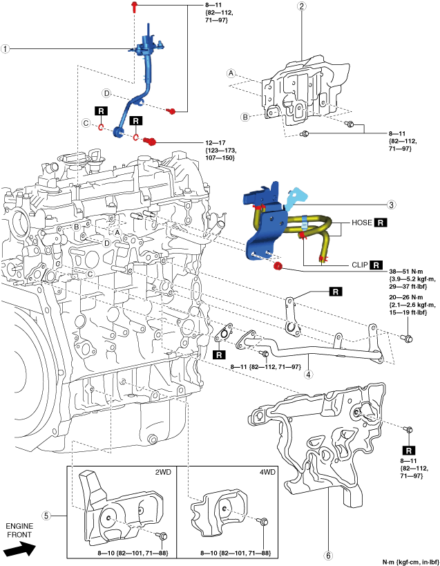
Step 1
ac5wzw00014350
|
|
1
|
Exhaust gas pressure sensor No.1 component
|
|
2
|
Exhaust insulator
|
|
3
|
Exhaust gas pressure sensor No.2 component
|
|
4
|
Water pipe
|
|
5
|
Seal rubber
|
|
6
|
Noise suppression cover (No.3)
|
Step 2
ac5wzw00009334
|
|
1
|
Insulator
|
|
2
|
Seal plate
|
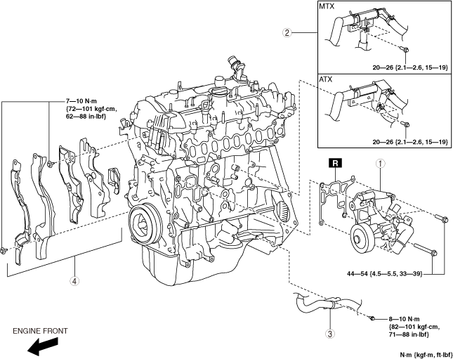
Step 3
ac5wzw00009335
|
|
1
|
Water pump component
|
|
2
|
Water pipe
|
|
3
|
Water hose and pipe (ATX)
|
|
4
|
Noise suppression cover (No.1), noise suppression cover (No.2), seal rubber
|
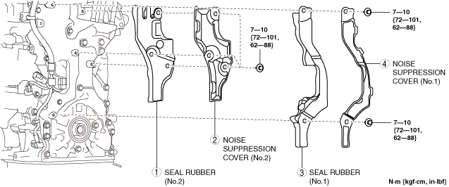
Noise Suppression Cover (No.1), Noise Suppression Cover (No.2), Seal Rubber Removal Note
1. Remove the noise suppression covers and seal rubbers in the order shown in the figure.
ac5wzw00009336
|
2. Remove the wiring harness using the following procedure:
ac5wzw00009337
|
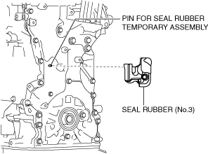
3. Remove the seal rubber (No.3).
ac5wzw00009338
|
Noise Suppression Cover (No.1), Noise Suppression Cover (No.2), Seal Rubber Installation Note
1. Temporarily put the seal rubber (No.3) on the engine front cover.
ac5wzw00009338
|
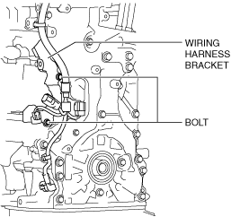
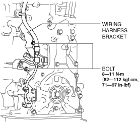
2. Install the wiring harness and wiring harness bracket.
ac5wzw00009339
|
3. Install the noise suppression covers and seal rubbers in the order shown in the figure.
ac5wzw00009340
|
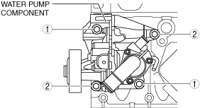
Water Pump Component Installation Note
1. Tighten the water pump component installation bolts in the order shown in the figure.
ac5wzw00006604
|
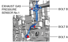
Exhaust Gas Pressure Sensor No.1 Installation Note
1. Temporarily tighten the bolt.
ac5wzw00009341
|
2. Tighten the bolt A.
3. Tighten the bolt B.