1. : Mazda SST number
2. : Global SST number
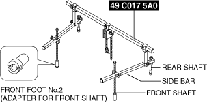
1: 49 C017 5A0
2: –
Engine support set

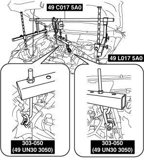
1: 49 UN30 3050
2: 303–050
Engine lifting bracket
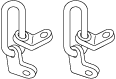
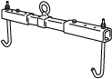
1: 49 L017 5A0
2: –
Support hanger
AUTOMATIC TRANSAXLE REMOVAL/INSTALLATION [GW6A-EL]
id0517i21172i1
Special Service Tool (SST)
|
1. : Mazda SST number
2. : Global SST number
|
|||||
|
1: 49 C017 5A0
2: –
Engine support set
|
|
1: 49 UN30 3050
2: 303–050
Engine lifting bracket
|
|
1: 49 L017 5A0
2: –
Support hanger
|
|
Removal
1. Disconnect the negative battery terminal. (See NEGATIVE BATTERY TERMINAL DISCONNECTION/CONNECTION.)
2. Remove the engine cover. (See ENGINE COVER REMOVAL/INSTALLATION [SKYACTIV-D 2.2].)
3. Remove the air cleaner component. (See INTAKE-AIR SYSTEM REMOVAL/INSTALLATION [SKYACTIV-D 2.2].)
4. Remove the battery and battery tray. (See BATTERY REMOVAL/INSTALLATION [SKYACTIV-D 2.2].)
5. Remove the splash shield. (See SPLASH SHIELD REMOVAL/INSTALLATION.)
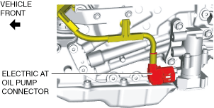
6. Disconnect the electric AT oil pump connector.
ac5wzw00009177
|
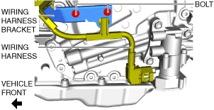
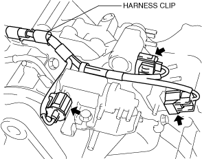
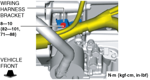
7. Remove the bolts and set the wiring harness and wiring harness bracket in a place which does not interfere with servicing.
ac5wzw00010986
|
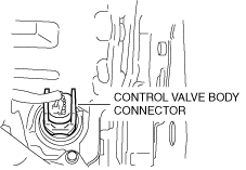
8. Disconnect the control valve body connector.
ac5wzw00009179
|
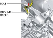
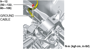
9. Disconnect the ground cable.
ac5wzw00009180
|
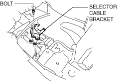
10. Disconnect the selector cable from the transaxle. (See SELECTOR LEVER COMPONENT REMOVAL/INSTALLATION.)
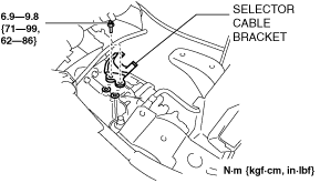
11. Remove the selector cable bracket.
ac5wzw00009182
|
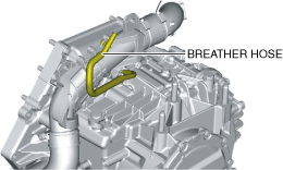
12. Disconnect the breather hose from the transaxle.
ac5wzw00009183
|
13. Remove the joint cover. (See STEERING WHEEL AND COLUMN REMOVAL/INSTALLATION.)
14. Disconnect the intermediate shaft from the steering gear and linkage. (See STEERING WHEEL AND COLUMN REMOVAL/INSTALLATION.)
15. Drain the engine coolant. (See ENGINE COOLANT REPLACEMENT [SKYACTIV-D 2.2].)
16. Remove the EGR cooler. (See EGR COOLER REMOVAL/INSTALLATION [SKYACTIV-D 2.2].)
17. Disconnect the solenoid valve connectors and the wiring harness from the solenoid valve component. (SKYACTIV-D 2.2 (Fuel injector (2pin type))) (See COMPRESSOR BYPASS SOLENOID VALVE REMOVAL/INSTALLATION [SKYACTIV-D 2.2].) (See REGULATING SOLENOID VALVE REMOVAL/INSTALLATION [SKYACTIV-D 2.2].) (See WASTEGATE SOLENOID VALVE REMOVAL/INSTALLATION [SKYACTIV-D 2.2].)
ac5wzw00009184
|
18. Disconnect the solenoid valve component from the ATX with the hose still connected, and set it out of the way. (SKYACTIV-D 2.2 (Fuel injector (2pin type))) (See COMPRESSOR BYPASS SOLENOID VALVE REMOVAL/INSTALLATION [SKYACTIV-D 2.2].) (See REGULATING SOLENOID VALVE REMOVAL/INSTALLATION [SKYACTIV-D 2.2].) (See WASTEGATE SOLENOID VALVE REMOVAL/INSTALLATION [SKYACTIV-D 2.2].)
ac5wzw00009185
|
19. Remove the front tires. (See WHEEL AND TIRE REMOVAL/INSTALLATION.)
20. Remove the front under cover No.2. (See FRONT UNDER COVER No.2 REMOVAL/INSTALLATION.)
21. Remove the front under cover No.1. (See FRONT UNDER COVER No.1 REMOVAL/INSTALLATION.)
22. Drain the ATF. (See AUTOMATIC TRANSAXLE FLUID (ATF) REPLACEMENT [GW6A-EL, GW6AX-EL].)
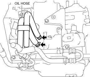
23. Disconnect the oil hoses from the transaxle. (With oil cooler No.2) (See OIL COOLER REMOVAL/INSTALLATION [GW6A-EL, GW6AX-EL (SKYACTIV-D 2.2)].)
ac5wzw00009497
|
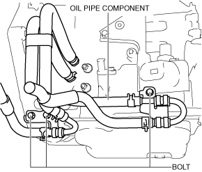
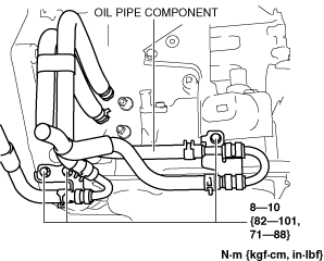
24. Remove the bolts shown in the figure and set the oil pipe component in a place which does not interfere with the servicing. (With oil cooler No.2) (See OIL COOLER REMOVAL/INSTALLATION [GW6A-EL, GW6AX-EL (SKYACTIV-D 2.2)].)
ac5wzw00009498
|
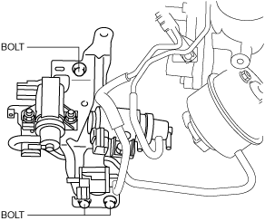
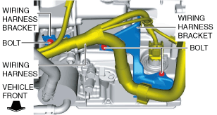
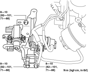
25. Remove the bolts and set the wiring harness and wiring harness bracket in a place which does not interfere with servicing.
ac5wzw00010987
|
26. Disconnect the oil cooler from the transaxle with the hose connected. (Except Automatic Transaxle Replacement) (See OIL COOLER REMOVAL/INSTALLATION [GW6A-EL, GW6AX-EL (SKYACTIV-D 2.2)].)
27. Disconnect the water hose from the oil cooler. (Automatic Transaxle Replacement) (See OIL COOLER REMOVAL/INSTALLATION [GW6A-EL, GW6AX-EL (SKYACTIV-D 2.2)].)
28. Remove the starter. (See STARTER REMOVAL/INSTALLATION [SKYACTIV-D 2.2].)
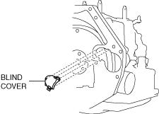
29. Remove the blind cover.
ac5wzw00009187
|
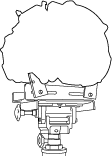
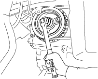
30. Hold the crankshaft pulley to prevent drive plate from rotating.
ac5jjw00003168
|
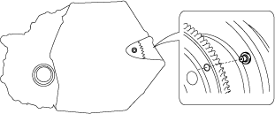
31. Remove the torque converter nuts from the starter installation hole.
ac5jjw00003050
|
32. Disconnect the front ABS wheel-speed sensors from the steering knuckles. (See FRONT ABS WHEEL-SPEED SENSOR REMOVAL/INSTALLATION.)
33. Disconnect the clips securing the brake hose from the front shock absorbers. (See FRONT BRAKE HOSE REMOVAL/INSTALLATION [WITH SINGLE PISTON FLOATING CALIPER].) (See FRONT BRAKE HOSE REMOVAL/INSTALLATION [WITH 2-PISTON FLOATING CALIPER].)
34. Disconnect the tie-rod end ball joints from the steering knuckles. (See STEERING GEAR AND LINKAGE REMOVAL/INSTALLATION.)
35. Disconnect the front lower arms from the steering knuckles. (See FRONT LOWER ARM REMOVAL/INSTALLATION.)
36. Disconnect the front stabilizer control links from the front stabilizer. (See FRONT STABILIZER REMOVAL/INSTALLATION.)
37. Disconnect the front drive shaft (LH) from the transaxle. (See FRONT DRIVE SHAFT REMOVAL/INSTALLATION.)
38. Disconnect the front drive shaft (RH) from the transaxle. (See FRONT DRIVE SHAFT REMOVAL/INSTALLATION.)
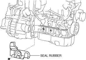
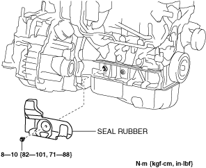
39. Remove the seal rubber.
ac5wzw00004300
|
40. Remove the front crossmember component and No.1 engine mount rubber as a single unit. (See FRONT CROSSMEMBER REMOVAL/INSTALLATION.)
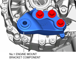
41. Remove the No.1 engine mounting bracket component.
ac5wzw00009188
|
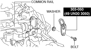
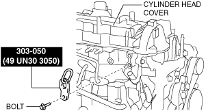
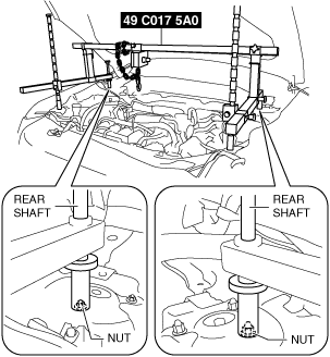
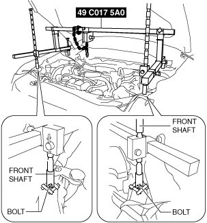
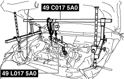
42. Install the SST using the following procedures.
ac5wzw00009189
|
ac5wzw00009190
|
ac5wzw00009191
|
Engine front side
ac5wzw00009192
|
Engine rear side
ac5wzw00009193
|
ac5wzw00009194
|
ac5wzw00012860
|
ac5jjw00010787
|
ac5jjw00010788
|
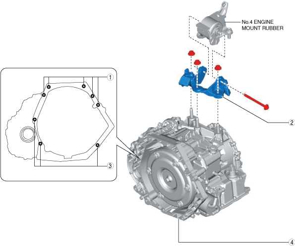
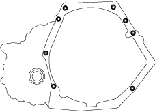
43. Remove in the order shown in the figure.
ac5wzw00009196
|
|
1
|
Transaxle mounting bolts (upper side)
|
|
2
|
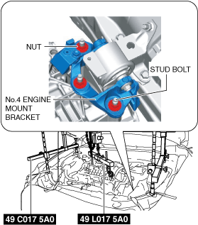
No.4 engine mount bracket
|
|
3
|
Transaxle mounting bolts (lower side)
|
|
4
|
Transaxle
|
No.4 engine mount bracket removal note
1. Place alignment marks on the locations shown in the figure so that they can be assembled to the same positions as before removal.
ac5wzw00009197
|
2. Remove the No.4 engine mount bracket.
Transaxle mounting bolt removal note
1. Adjust the SST and lean the engine toward the transaxle.
ac5jjw00010787
|
2. Support the transaxle on a jack.
ac5jjw00003179
|
3. Remove the transaxle mounting bolts (lower side).
4. Remove the transaxle.
Installation
1. Verify that the torque converter stud bolts are inserted into the drive plate bolt holes from the starter installation hole.
ac5jjw00003065
|
2. Install the transaxle mounting bolts.
ac5jjw00003066
|
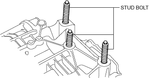
3. Tighten the stud bolts for the transaxle.
ac5wzw00009198
|
4. Install the No.4 engine mount bracket to No.4 engine mount rubber, and temporarily tighten the installation bolt.
ac5wzw00009199
|
5. Lift up the transaxle using the SSTs, pass the transaxle stud bolts through the No.4 engine mount bracket, and temporarily tighten the No.4 engine mount bracket installation nuts.
ac5wzw00009200
|
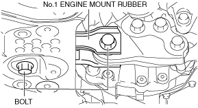
6. Install the No.1 engine mount bracket component, and tighten the installation bolts in the order shown in the figure.
ac5wzw00009201
|
7. Install the front crossmember component and No.1 engine mount rubber as a single unit. (See FRONT CROSSMEMBER REMOVAL/INSTALLATION.)
8. Temporarily tighten the No.1 engine mount rubber installation bolts.
ac5wzw00009202
|
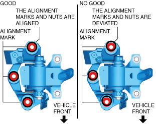
9. Align the positions of the No.4 engine mount bracket installation nuts with the No.4 engine mount bracket.
ac5wzw00009203
|
10. Tighten the No.4 engine mount bracket installation nuts and bolt in the order shown in the figure.
ac5wzw00009204
|
|
No. |
Tightening torque |
|---|---|
|
1, 2, 3
|
92—116 N·m {9.4—11 kgf·m, 69—85 ft·lbf}
|
|
4
|
81—99 N·m {8.3—10 kgf·m, 60—73 ft·lbf}
|
11. Remove the SST (49 C017 5A0).
12. Tighten the No.1 engine mount rubber installation bolts in the order shown in the figure.
ac5wzw00009205
|
|
No. |
Tightening torque |
|---|---|
|
1
|
141—172 N·m {15—17 kgf·m, 104—126 ft·lbf}
|
|
2
|
130—164 N·m {14—16 kgf·m, 96—120 ft·lbf}
|
13. Fix the crankshaft pulley to lock the torque converter against rotation.
ac5jjw00003185
|
14. Tighten the torque converter installation nut.
ac5jjw00003186
|
15. Install the blind cover.
ac5wzw00009206
|
16. Install the starter. (See STARTER REMOVAL/INSTALLATION [SKYACTIV-D 2.2].)
17. Install the seal rubber.
ac5wzw00009622
|
18. Connect the front drive shaft (RH) to the transaxle. (See FRONT DRIVE SHAFT REMOVAL/INSTALLATION.)
19. Connect the front drive shaft (LH) to the transaxle. (See FRONT DRIVE SHAFT REMOVAL/INSTALLATION.)
20. Connect the front stabilizer control links to the front stabilizer. (See FRONT STABILIZER REMOVAL/INSTALLATION.)
21. Connect the front lower arms to the steering knuckles. (See FRONT LOWER ARM REMOVAL/INSTALLATION.)
22. Connect the tie-rod end ball joints to the steering knuckles. (See STEERING GEAR AND LINKAGE REMOVAL/INSTALLATION.)
23. Connect the clips securing the brake hose to the front shock absorbers. (See FRONT BRAKE HOSE REMOVAL/INSTALLATION [WITH SINGLE PISTON FLOATING CALIPER].) (See FRONT BRAKE HOSE REMOVAL/INSTALLATION [WITH 2-PISTON FLOATING CALIPER].)
24. Connect the front ABS wheel-speed sensors to the steering knuckles. (See FRONT ABS WHEEL-SPEED SENSOR REMOVAL/INSTALLATION.)
25. Connect the water hose to the oil cooler. (Automatic Transaxle Replacement) (See OIL COOLER REMOVAL/INSTALLATION [GW6A-EL, GW6AX-EL (SKYACTIV-D 2.2)].)
26. Connect the oil cooler to the transaxle with the hose connected. (Except Automatic Transaxle Replacement) (See OIL COOLER REMOVAL/INSTALLATION [GW6A-EL, GW6AX-EL (SKYACTIV-D 2.2)].)
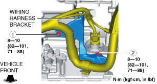
27. Install the wiring harness bracket.
ac5wzw00010988
|
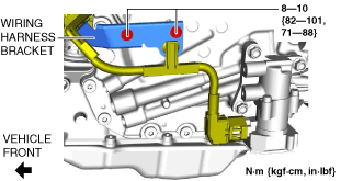
28. Tighten the wiring harness bracket installation bolts in the order shown in the figure.
ac5wzw00010989
|
29. Install the oil pipe component. (With oil cooler No.2) (See OIL COOLER REMOVAL/INSTALLATION [GW6A-EL, GW6AX-EL (SKYACTIV-D 2.2)].)
ac5wzw00009499
|
30. Connect the oil hose to the transaxle. (With oil cooler No.2) (See OIL COOLER REMOVAL/INSTALLATION [GW6A-EL, GW6AX-EL (SKYACTIV-D 2.2)].)
ac5wzw00009500
|
31. Install the front under cover No.1. (See FRONT UNDER COVER No.1 REMOVAL/INSTALLATION.)
32. Install the front under cover No.2. (See FRONT UNDER COVER No.2 REMOVAL/INSTALLATION.)
33. Install the front tires. (See WHEEL AND TIRE REMOVAL/INSTALLATION.)
34. Install the insulator. (SKYACTIV-D 2.2 (Fuel injector (2pin type))) (See TIMING CHAIN REMOVAL/INSTALLATION [SKYACTIV-D 2.2].)
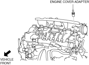
35. Install the engine cover adapter.
ac5wzw00009208
|
36. Connect the solenoid valve component. (SKYACTIV-D 2.2 (Fuel injector (2pin type))) (See COMPRESSOR BYPASS SOLENOID VALVE REMOVAL/INSTALLATION [SKYACTIV-D 2.2].) (See REGULATING SOLENOID VALVE REMOVAL/INSTALLATION [SKYACTIV-D 2.2].) (See WASTEGATE SOLENOID VALVE REMOVAL/INSTALLATION [SKYACTIV-D 2.2].)
ac5wzw00009209
|
37. Connect the solenoid valve connectors and the wiring harness to the solenoid valve component. (SKYACTIV-D 2.2 (Fuel injector (2pin type))) (See COMPRESSOR BYPASS SOLENOID VALVE REMOVAL/INSTALLATION [SKYACTIV-D 2.2].) (See REGULATING SOLENOID VALVE REMOVAL/INSTALLATION [SKYACTIV-D 2.2].) (See WASTEGATE SOLENOID VALVE REMOVAL/INSTALLATION [SKYACTIV-D 2.2].)
ac5wzw00009184
|
38. Install the EGR cooler. (See EGR COOLER REMOVAL/INSTALLATION [SKYACTIV-D 2.2].)
39. Connect the intermediate shaft to the steering gear and linkage. (See STEERING WHEEL AND COLUMN REMOVAL/INSTALLATION.)
40. Install the joint cover. (See STEERING WHEEL AND COLUMN REMOVAL/INSTALLATION.)
41. Connect the breather hose to the transaxle.
ac5wzw00009183
|
42. Install the selector cable bracket.
ac5wzw00011787
|
43. Connect the selector cable to the transaxle. (See SELECTOR LEVER COMPONENT REMOVAL/INSTALLATION.)
44. Connect the ground cable to the No.4 engine mount bracket.
ac5wzw00009210
|
45. Connect the control valve body connector.
ac5wzw00009212
|
46. Install the wiring harness bracket.
ac5wzw00010990
|
47. Connect the electric AT oil pump connector.
ac5wzw00009177
|
48. Install the splash shield. (See SPLASH SHIELD REMOVAL/INSTALLATION.)
49. Install the battery and battery tray. (See BATTERY REMOVAL/INSTALLATION [SKYACTIV-D 2.2].)
50. Install the air cleaner component. (See INTAKE-AIR SYSTEM REMOVAL/INSTALLATION [SKYACTIV-D 2.2].)
51. Connect the negative battery terminal. (See NEGATIVE BATTERY TERMINAL DISCONNECTION/CONNECTION.)
52. Refill the engine coolant. (See ENGINE COOLANT REPLACEMENT [SKYACTIV-D 2.2].)
53. Add the ATF. (See AUTOMATIC TRANSAXLE FLUID (ATF) REPLACEMENT [GW6A-EL, GW6AX-EL].)
54. Install the engine cover. (See ENGINE COVER REMOVAL/INSTALLATION [SKYACTIV-D 2.2].)
55. Perform the “TCM configuration” (Automatic transaxle replacement). (See TCM CONFIGURATION [GW6A-EL, GW6AX-EL])
56. Perform the “Initial Learning” (automatic transaxle replacement). (See INITIAL LEARNING [GW6A-EL, GW6AX-EL].)
57. Perform the “Mechanical System Test”. (See MECHANICAL SYSTEM TEST [GW6A-EL, GW6AX-EL].)