SELECTOR CABLE REMOVAL/INSTALLATION
id051800297700
1. Disconnect the negative battery terminal. (See NEGATIVE BATTERY TERMINAL DISCONNECTION/CONNECTION.)
2. Perform the following procedure to remove the selector cable (transaxle side).
- (1) Remove the air cleaner component. (See INTAKE-AIR SYSTEM REMOVAL/INSTALLATION [WITHOUT CYLINDER DEACTIVATION (SKYACTIV-G 2.0, SKYACTIV-G 2.5)].) (See INTAKE-AIR SYSTEM REMOVAL/INSTALLATION [WITH CYLINDER DEACTIVATION (SKYACTIV-G 2.0, SKYACTIV-G 2.5)].) (See INTAKE-AIR SYSTEM REMOVAL/INSTALLATION [SKYACTIV-G 2.5T].) (See INTAKE-AIR SYSTEM REMOVAL/INSTALLATION [SKYACTIV-D 2.2].)
-
- (2) Remove the battery. (See BATTERY REMOVAL/INSTALLATION [WITHOUT CYLINDER DEACTIVATION (SKYACTIV-G 2.0, SKYACTIV-G 2.5)].) (See BATTERY REMOVAL/INSTALLATION [WITH CYLINDER DEACTIVATION (SKYACTIV-G 2.0, SKYACTIV-G 2.5)].) (See BATTERY REMOVAL/INSTALLATION [SKYACTIV-G 2.5T].) (See BATTERY REMOVAL/INSTALLATION [SKYACTIV-D 2.2].)
-
- (3) Remove the PCM component. (FW6A-EL, FW6AX-EL) (See PCM REMOVAL/INSTALLATION [WITHOUT CYLINDER DEACTIVATION (SKYACTIV-G 2.0, SKYACTIV-G 2.5)].) (See PCM REMOVAL/INSTALLATION [WITH CYLINDER DEACTIVATION (SKYACTIV-G 2.0, SKYACTIV-G 2.5)].)
-
- (4) Remove the battery tray. (See BATTERY REMOVAL/INSTALLATION [WITHOUT CYLINDER DEACTIVATION (SKYACTIV-G 2.0, SKYACTIV-G 2.5)].) (See BATTERY REMOVAL/INSTALLATION [WITH CYLINDER DEACTIVATION (SKYACTIV-G 2.0, SKYACTIV-G 2.5)].) (See BATTERY REMOVAL/INSTALLATION [SKYACTIV-G 2.5T].) (See BATTERY REMOVAL/INSTALLATION [SKYACTIV-D 2.2].)
-
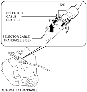
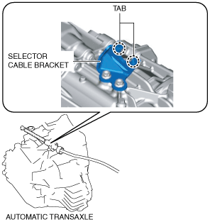
- (5) While pressing the selector cable bracket tab in the direction of the arrow (1) shown in the figure, lift up the cable outer end (transaxle side) in the direction of the arrow (2) shown in the figure to detach the selector cable bracket tab from the cable outer end (transaxle side).
-
- (6) Disconnect the cable outer end (transaxle side) from the selector cable bracket. (See Cable Outer End (Transaxle Side) Installation Note.)
-
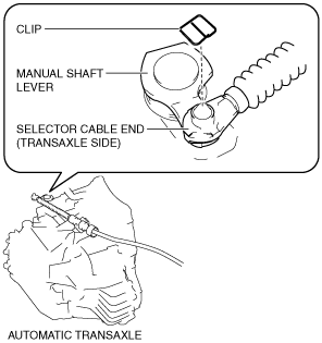
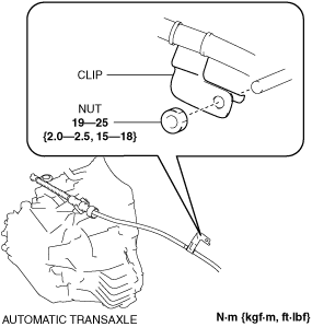
- (7) Remove the clip from the selector cable end (transaxle side). (See Selector Cable End (Transaxle Side) Installation Note.)
-
-
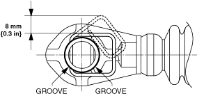
Caution
-
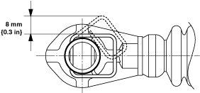
• Pull the clip within the range shown in the figure. If the clip is pulled excessively, it could deform and no longer function.
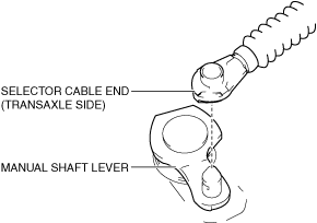
- (8) Disconnect the selector cable end (transaxle side) from the manual shaft lever.
-
3. Disconnect the clip as shown in the figure and remove the nut.
4. Perform the following procedure to remove the selector cable (selector lever side).
- (1) Remove the console side panel. (See CONSOLE SIDE PANEL REMOVAL/INSTALLATION.)
-
- (2) Remove the switch panel. (See SWITCH PANEL REMOVAL/INSTALLATION.)
-
- (3) Remove the cup holder. (See CUP HOLDER REMOVAL/INSTALLATION.)
-
- (4) Remove the selector lever knob. (See SELECTOR LEVER COMPONENT REMOVAL/INSTALLATION.)
-
- (5) Remove the shift panel. (See SHIFT PANEL REMOVAL/INSTALLATION.)
-
- (6) Remove the front console box. (See FRONT CONSOLE BOX REMOVAL/INSTALLATION.)
-
- (7) Remove the side wall. (See SIDE WALL REMOVAL/INSTALLATION.)
-
- (8) Remove the rear console. (See REAR CONSOLE REMOVAL/INSTALLATION.)
-
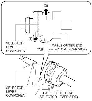
- (9) While pressing the cable outer end tab (selector lever side) in the direction of the arrow (1) shown in the figure, lift up cable outer end (selector lever side) in the direction of the arrow (2) shown in the figure to detach the cable outer end tab (selector lever side) from the selector lever component.
-
- (10) Disconnect the cable outer end (selector lever side) from the selector lever component.
-
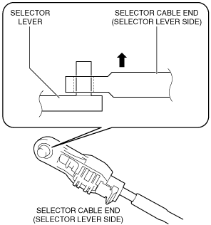
- (11) Disconnect the selector cable end (selector lever side) from the selector lever. (See Selector Cable (Selector Lever Side) Installation Note.)
-
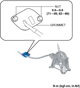
5. Disconnect the grommet as shown in the figure and remove the nuts.
6. Pull out the selector cable from inside the cabin and remove it.
7. Install in the reverse order of removal.
Selector Cable (Selector Lever Side) Installation Note
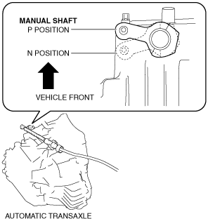
1. Verify that the selector lever is in the P position.
2. Verify that the manual shaft is in the P position.
Selector Cable End (Transaxle Side) Installation Note
-
Caution
-
• Pull the clip within the range shown in the figure. If the clip is pulled excessively, it could deform and no longer function.
1. Install a clip to the groove of the selector cable end (transaxle side).
Cable Outer End (Transaxle Side) Installation Note
1. Verify that the selector cable bracket tabs are not deformed.
-
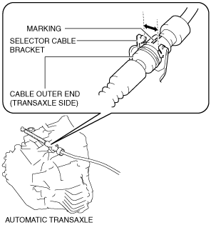
2. Assemble the cable outer end (transaxle side) to the selector cable bracket so that the marking is in the area of the arrow shown in the figure.